Grease Guide

a technology of grease guide and lubricant, which is applied in the direction of rail wetting/lubrication, rail lubrication, rail components, etc., can solve the problems of reducing the efficiency of lubricant transfer to the train wheels, reducing the effectiveness of the trough, and reducing the efficiency of the trough transfer

Inactive Publication Date: 2008-09-18
PORTEC RAIL PRODS
View PDF14 Cites 27 Cited by
  • Summary
  • Abstract
  • Description
  • Claims
  • Application Information

AI Technical Summary

Problems solved by technology

Oftentimes with these rail lubrication systems, substantial amounts of lubricant is wasted by dripping or falling along the sides of the railroad rail thus reducing the efficiency of the lubricant transfer to the train wheels.
Oftentimes, the puddle of grease in the trough is splashed out when a deep wheel flange due to wearing o

Method used


Image

  • Grease Guide
  • Grease Guide
  • Grease Guide

Examples


Embodiment Construction

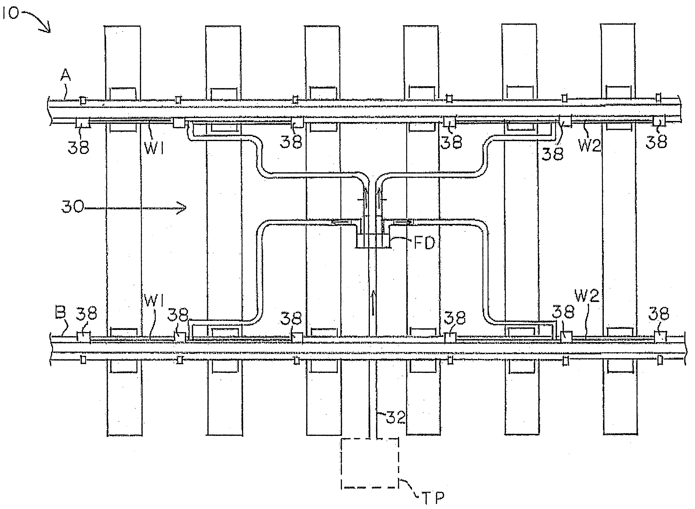
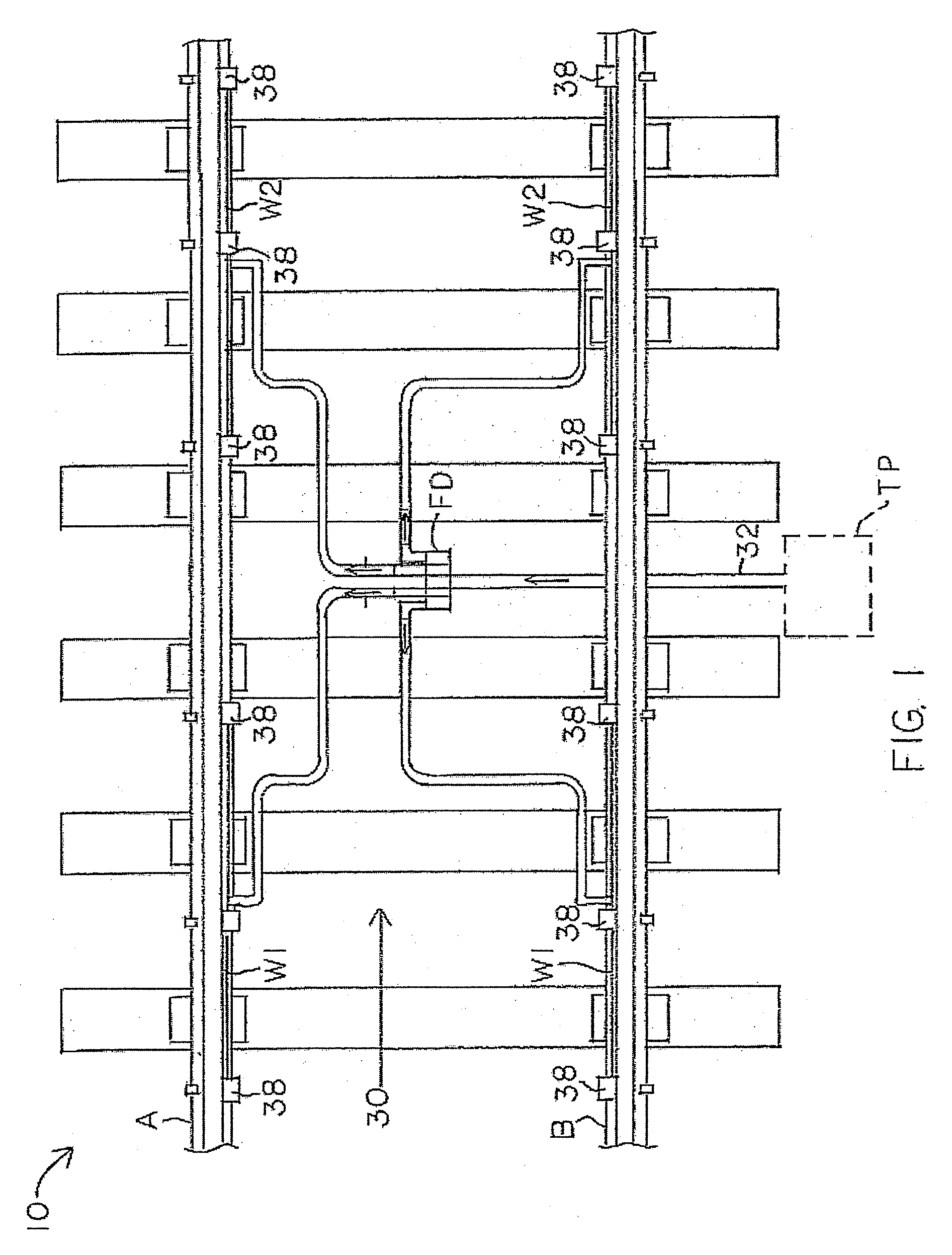
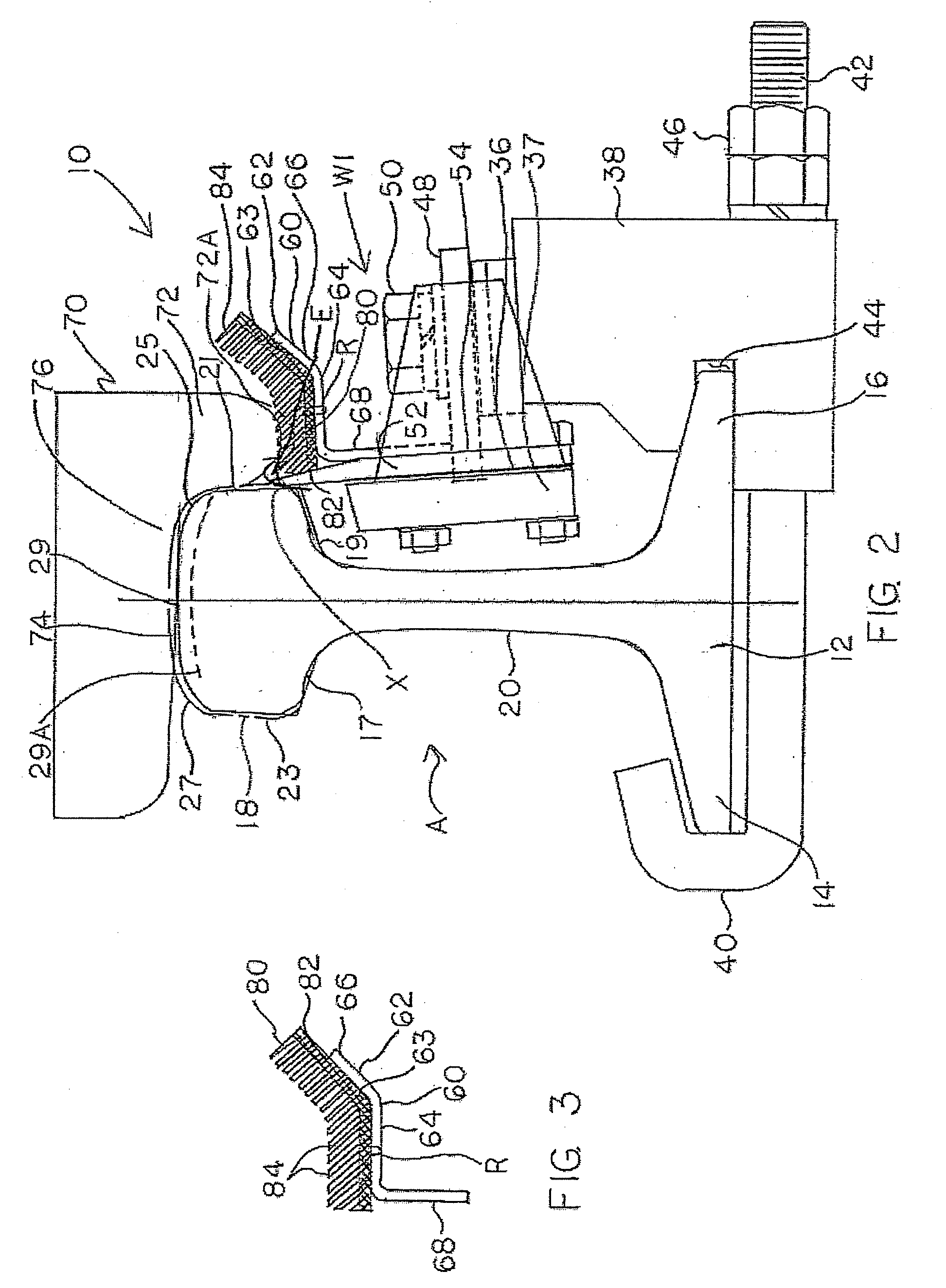
[0020]Referring to FIG. 1, the present invention provides for a rail lubrication system 10 that includes railroad rails A and B and wiping bar assemblies W1 and W2 secured thereto for applying friction modifying material to the railroad rails, Rail A and Rail B. The system 10 also includes a flow divider arrangement 30 in fluid communication with a lubricant tank containing a lubricant, such as grease, and a pump, via an inlet line 32. Such pump and tank arrangements are well known in the art and are designated as TP shown in phantom in FIG. 1. Referring to FIG. 2, Rail A, which is identical to Rail B, is a steel rail of usual cross-section and includes a base 12 having opposing flanges 14 and 16 extending therefrom. Rail A also includes a head 18 and a web 20 which secures the head 18 to the base 12. The head 18 has downwardly facing surfaces 17 and 19 on opposite sides of the web 20, generally vertical side surfaces or faces 21 and 23 (wherein side surface 21 is referred to as the...


PUM


Abstract

A trough for use on wiping bar assembly of a rail lubrication system, wherein the wiping bar assembly includes a manifold body and a flow passageway having an exit end at least partially defined in the manifold body. The trough includes a body having a first section and a second section extending away from the first section, wherein the first section of the body is positioned adjacent the exit end, and wherein a mat is provided within the trough.

Description

CROSS REFERENCE TO RELATED APPLICATIONS[0001]This application claims the benefit of U.S. Provisional Patent Application No. 60 / 902,538, filed Feb. 21, 2007, which is hereby incorporated by reference.BACKGROUND OF THE INVENTION[0002]1. Field of the Invention[0003]This invention relates to an apparatus for applying lubricant to a rail of a railroad track and, more particularly, to a lubricant distribution bar or wiping bar applicator for mounting on a railroad rail for application of lubricant thereto.[0004]2. Description of the Prior Art[0005]In the operation of railroads, it has long been the practice to apply lubricant or friction modifying materials onto railroad rails, such as to the top of the rails or sides of the rails at curves, turnouts, switches, and in some cases, thee sections of the track immediately before a switch, and periodically spaced along the length of the track. Such lubricants and friction modifying materials, such as grease, can either reduce or increase the f...

Claims


Application Information

Patent Timeline
IPC IPC(8): B61K3/00
CPCB61K3/00
Inventor SINGLETON, STEVEN D.URMSON, W. THOMASSCHNORR, CHARLES HENRYPOWELL, WARD T.PETRIE, CHARLES A.
Owner PORTEC RAIL PRODS
Why Eureka
Try Eureka