Orthopedic jig, pin, and method

a technology of orthopedic jigs and pins, applied in the field of surgical instruments, can solve the problems of adding several minutes or more to the total time of pinning

Inactive Publication Date: 2008-09-25
STRYKER EURO OPERATIONS HLDG LLC
View PDF29 Cites 14 Cited by
  • Summary
  • Abstract
  • Description
  • Claims
  • Application Information

AI Technical Summary

Problems solved by technology

As a result, the total time for pinning can add several minutes or more to a surgical procedure requiring a larger number of jigs.

Method used


Image

  • Orthopedic jig, pin, and method
  • Orthopedic jig, pin, and method
  • Orthopedic jig, pin, and method

Examples


Embodiment Construction

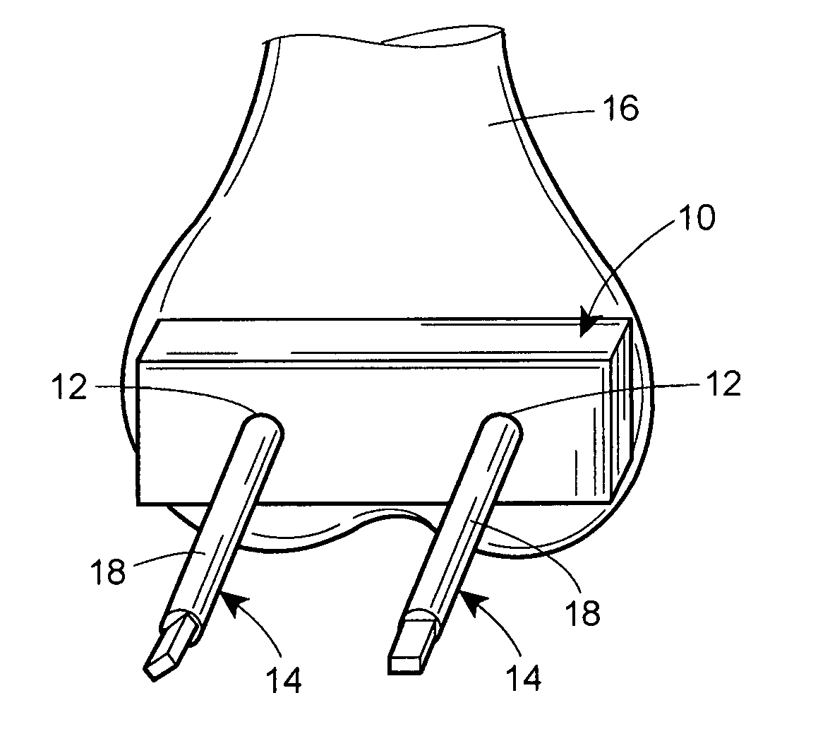
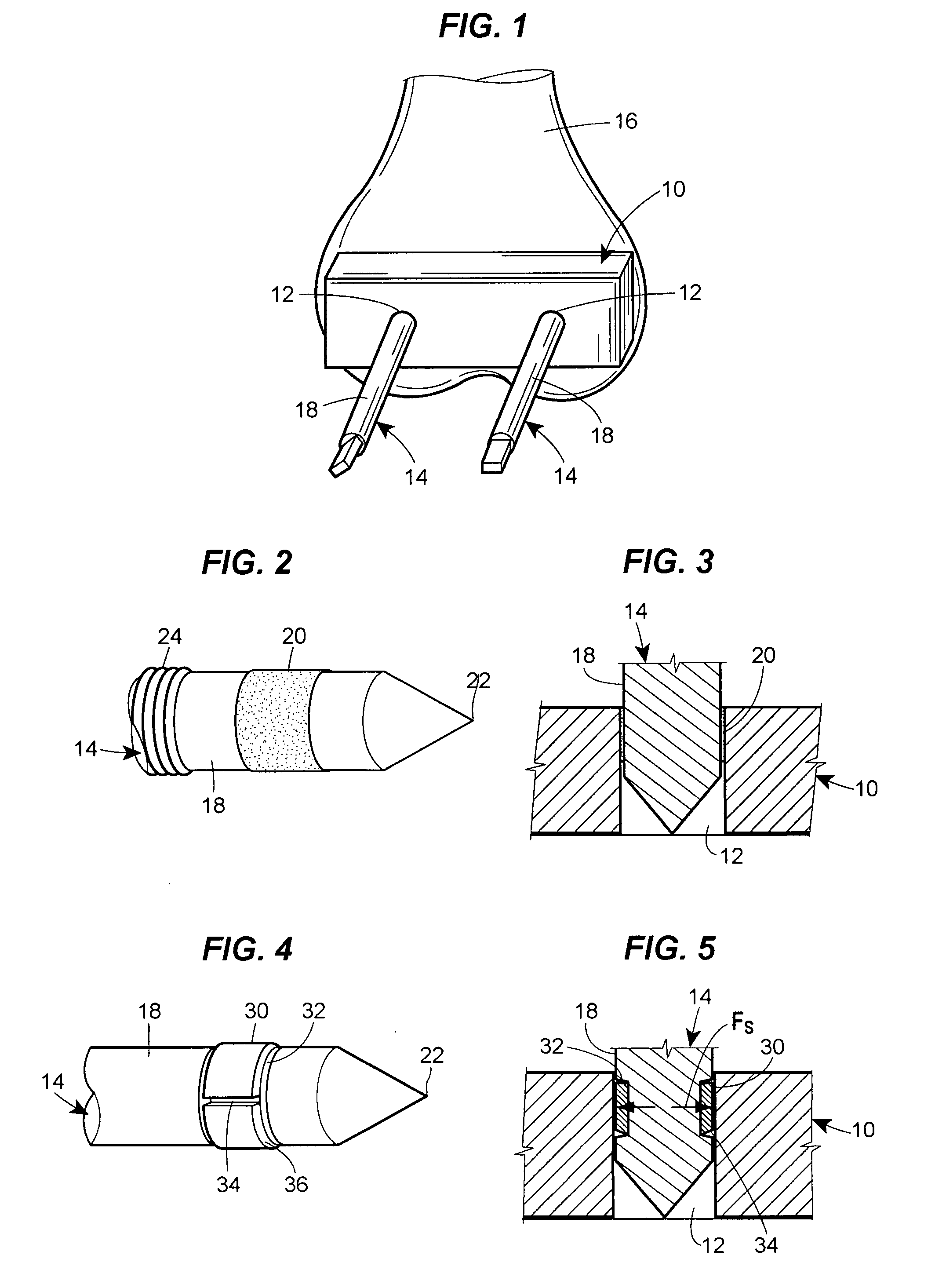
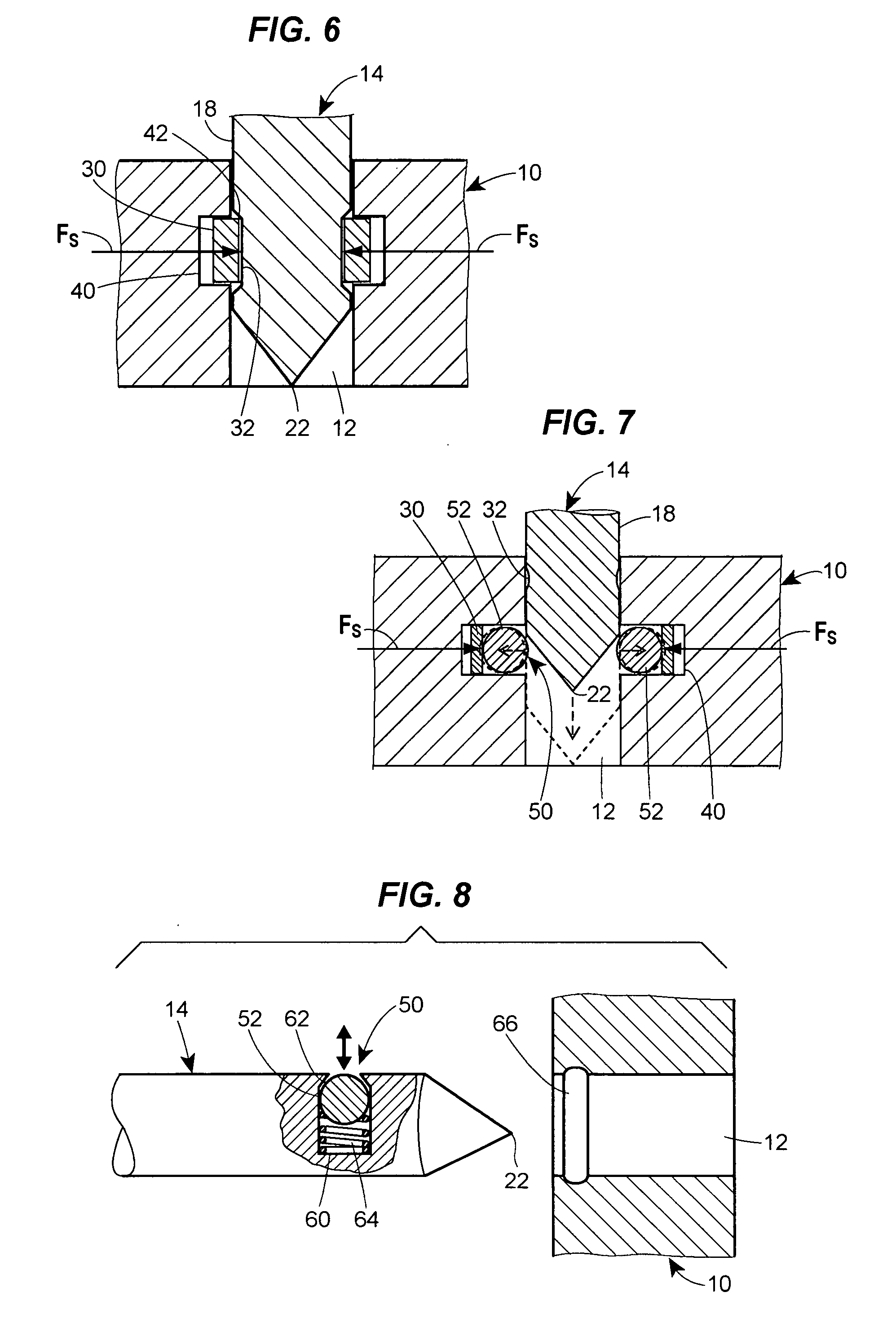
[0021]With reference to FIG. 1, a jig 10 for use in orthopedic surgical procedures includes apertures, such as through bores 12, for receiving pins 14 therethrough for attaching the jig to a work surface, such as a bone 16 during the surgical procedure. The pins 14 are releasably secured in the bores 12, such as by adhesive, clamping, and / or locking action, prior to attachment to the bone 16 by a restraining member associated with at least one of the jig 10 and the pin so that the pins may be pre-loaded within the bores in an area away from the surgical procedure by one person and subsequently engaged with the bone with the pre-loaded pins already releasably held within the bores by another person at the surgical procedure. Preferably, the restraining member is disposed and adapted so that an end of the pin 14 that is to be inserted into the bone is releasably retained within the bore 12, although in other embodiments the restraining member may be adapted to releasably retain the pi...


PUM


Abstract

An orthopedic jig and pins therefore are disclosed that allow the pins to be pre-loaded into apertures through the jig before the jig is positioned at a desired location with respect to a bone during an orthopedic surgical procedure. At least one of the pin and / or jig includes a retention mechanism whereby the pin can be inserted into the bore and releasably restrained therein until the jig is place in the selected position and the pins driven into the bone.

Description

CROSS REFERENCE TO RELATED APPLICATIONS[0001]Not applicableREFERENCE REGARDING FEDERALLY SPONSORED RESEARCH OR DEVELOPMENT[0002]Not applicableSEQUENTIAL LISTING [0003]Not applicableBACKGROUND OF THE INVENTION[0004]1. Field of the Invention[0005]The present invention relates to surgical instruments.[0006]2. Description of the Background of the Invention[0007]In orthopedic surgery, pins are regularly used to temporarily affix jigs, such as cutting blocks, to the bone. A standard technique for affixing a jig to a bone is for a surgeon to hold the jig to the bone, carefully insert the pins through apertures in the jig, and then drive the pins into the bone through the holes in order to achieve the fixation. The number of pins needed for affixing each jig varies typically between two and four, and often two or more jigs need to be temporarily affixed to the bone. Consequently, sometimes ten or more pins need to be inserted to the jigs and drilled into the bone during a surgical procedure...

Claims


Application Information

Patent Timeline
Patent Type & Authority Applications(United States)
IPC IPC(8): A61B17/04A61B17/58A61F5/00
CPCA61B17/17A61B17/15A61B2017/00862A61B2017/00951A61B17/1717
Inventor BRANDT, MATTSARVESTANI, AMIR
Owner STRYKER EURO OPERATIONS HLDG LLC
Why Eureka
Try Eureka