

Lane departure avoidance system
- Summary
- Abstract
- Description
- Claims
- Application Information
AI Technical Summary
Benefits of technology
Problems solved by technology
Method used
Image

Examples
Embodiment Construction
[0017]Selected embodiments of the present invention will now be explained with reference to the drawings. It will be apparent to those skilled in the art from this disclosure that the following descriptions of the embodiments of the present invention are provided for illustration only and not for the purpose of limiting the invention as defined by the appended claims and their equivalents.
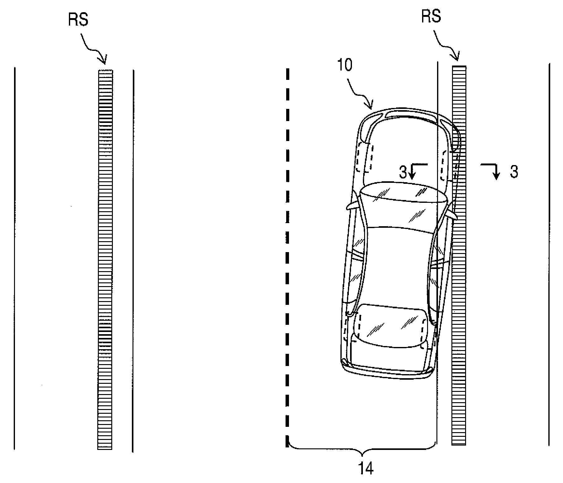
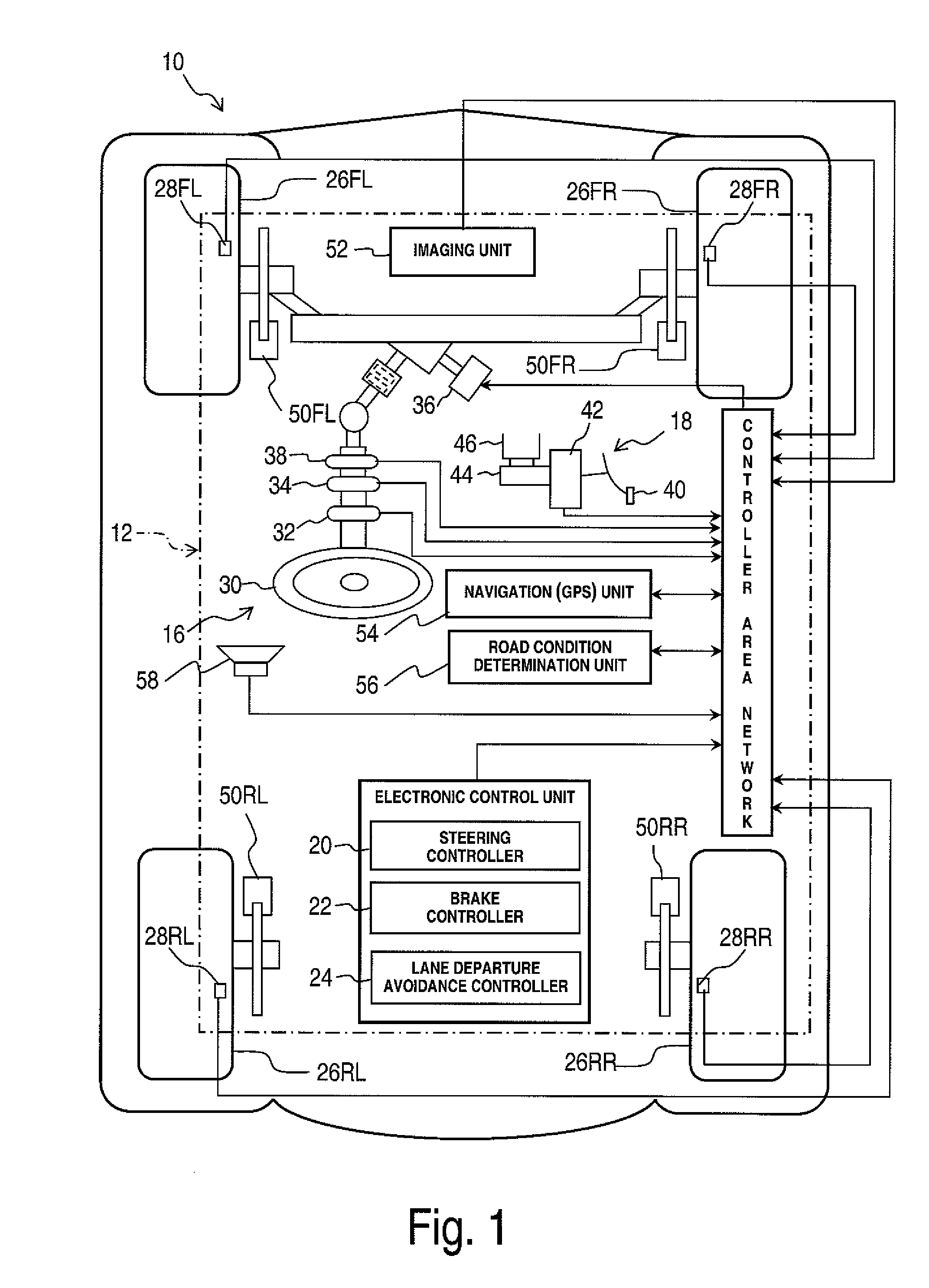
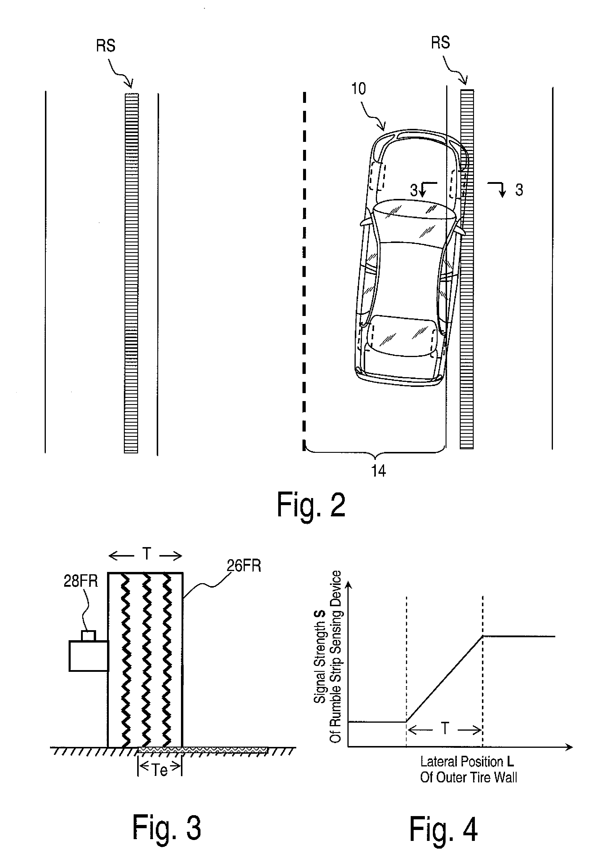
[0018]Referring initially to FIG. 1, a schematic diagram of a host vehicle 10 is illustrated that is equipped with a lane departure avoidance system 12 in accordance with one embodiment of the present invention. As seen in FIG. 2, a birds-eye view of the host vehicle 10 is illustrated that is engaging a rumble strip RS. FIG. 3 shows a schematic cross sectional view of the host vehicle's tire and the road as viewed along section line 3-3 of FIG. 2. As seen in FIG. 2, basically, the lane departure avoidance system 12 is configured to determine a lateral rate of lane departure of the host vehicle 10 f...
PUM
 Abstract
Description
Claims
Application Information