
Tube for heat exchanger and method of manufacturing tube

Inactive Publication Date: 2008-10-09
DENSO CORP
View PDF10 Cites 5 Cited by
  • Summary
  • Abstract
  • Description
  • Claims
  • Application Information

AI Technical Summary

Benefits of technology

[0010]In view of the foregoing problems, it is an object of the present invention to provide a tube for a heat exchanger and a method thereof, which can improve a pressure resistance and can be accurately brazed to a tank of the heat exchanger.
[0012]In a case where the tube is bonded to a tank of the heat exchanger by using a brazing material clad on the tank, the melted brazing material from the tank may enter into the tube by a capillary action. However, in the above tube, the melted brazing material only enters from a contact position where the other end portion of the single plate contacts the contact portion. Accordingly, it can prevent an insufficient bonding between the tube and the tank, thereby the tube can be accurately brazed to the tank.
[0013]The protruding portion can be used as an inner column portion in the tube. Because the protruding portion has a sectional dimension in the width direction, that is larger than two times of the wall thickness of the single plate, pressure resistance of the tube can be increased.
[0019]In a case where the tube is bonded to a tank of the heat exchanger by using a brazing material clad on the tank, the melted brazing material may enter into the tube by a capillary action. However, in the tube manufactured by the above method, the melted brazing material from the tank only enters from a contact position where the other end portion of the single plate contacts the contact portion. Accordingly, it can prevent an insufficient bonding between the tube and the tank, thereby the tube can be accurately brazed to the tank.

Problems solved by technology

In this case, a brazing material for bonding the tube and the core plate of the tank may become insufficient, thereby causing a brazing insufficient problem.

Method used


Image

  • Tube for heat exchanger and method of manufacturing tube
  • Tube for heat exchanger and method of manufacturing tube
  • Tube for heat exchanger and method of manufacturing tube

Examples


Embodiment Construction

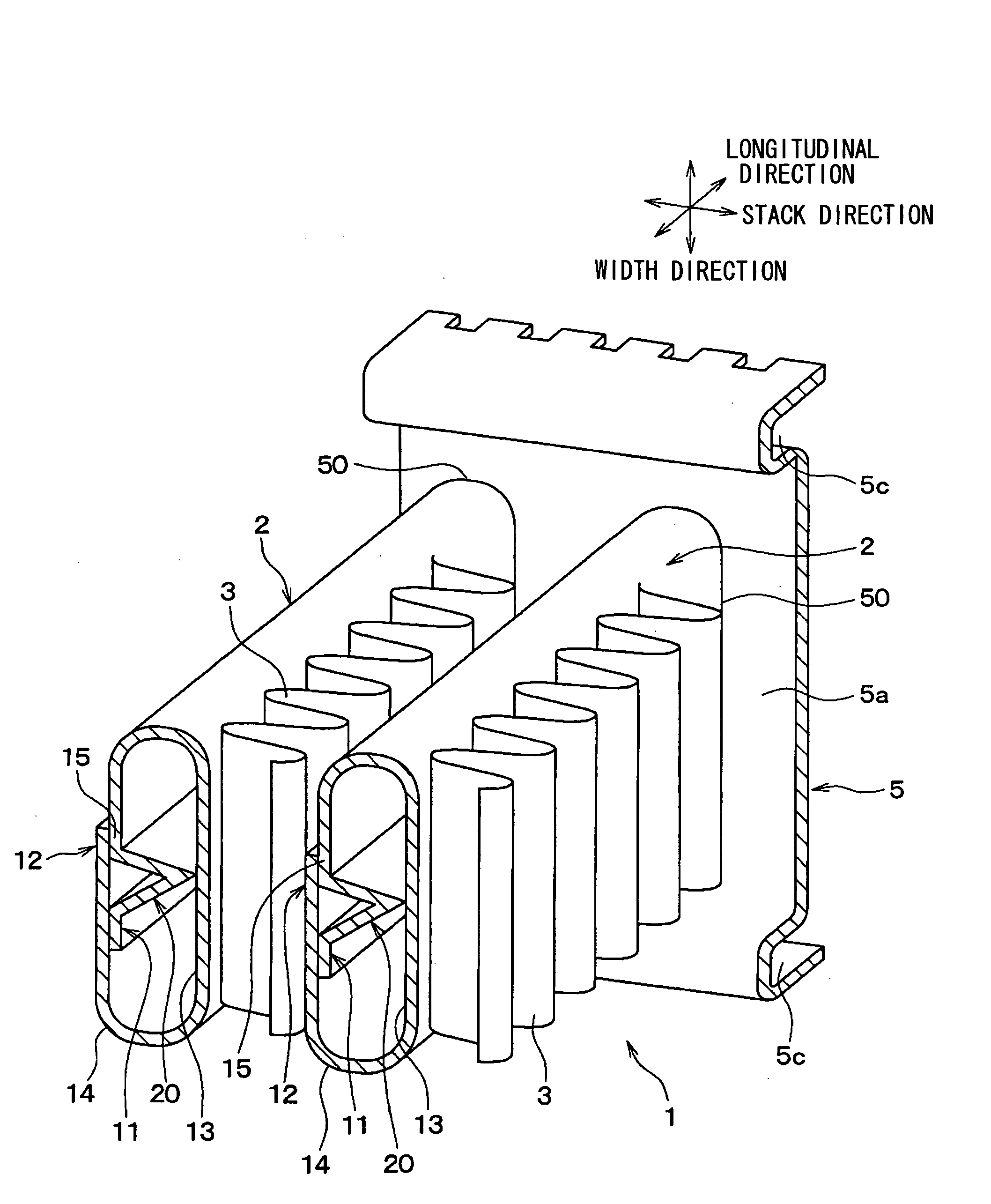
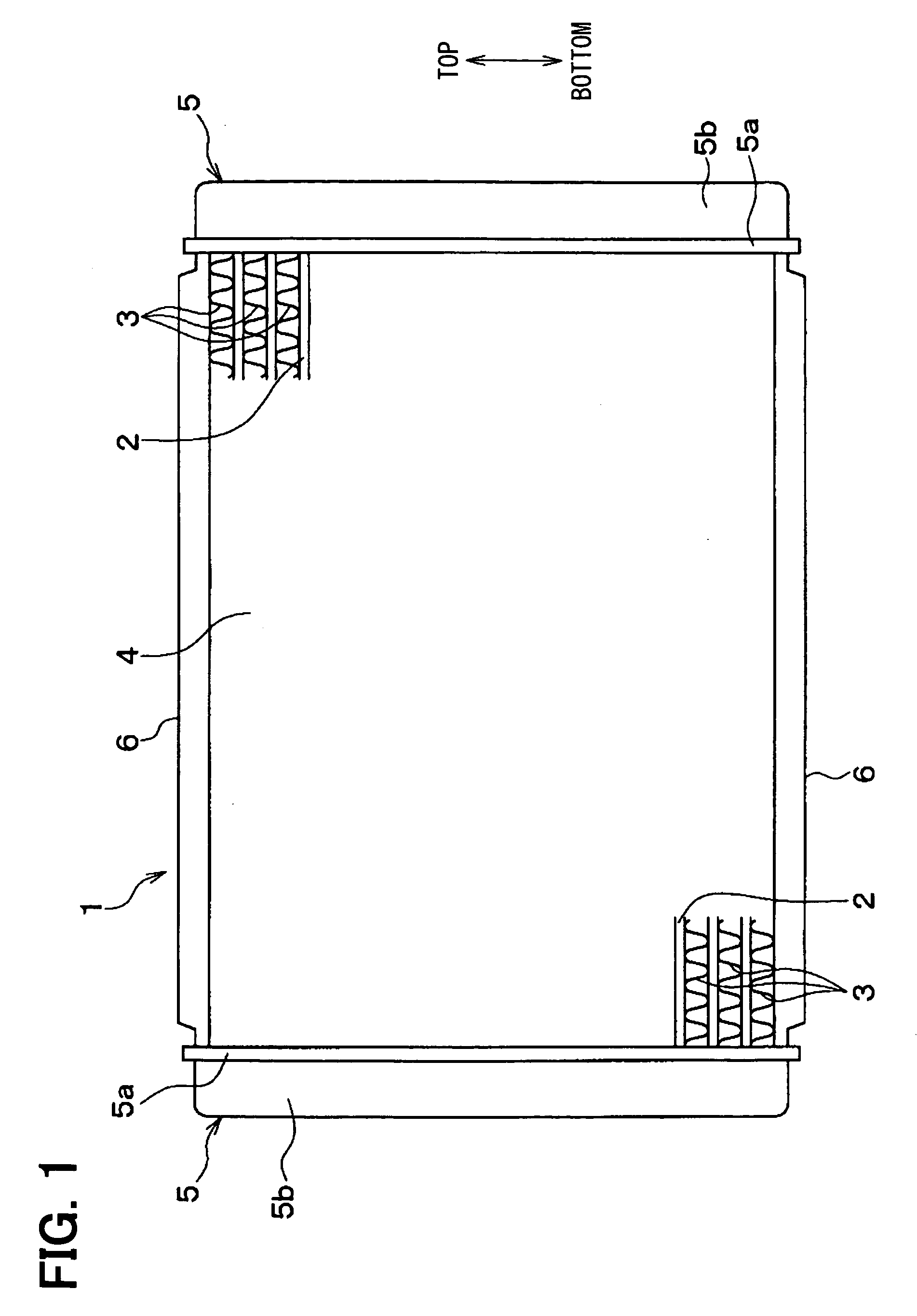
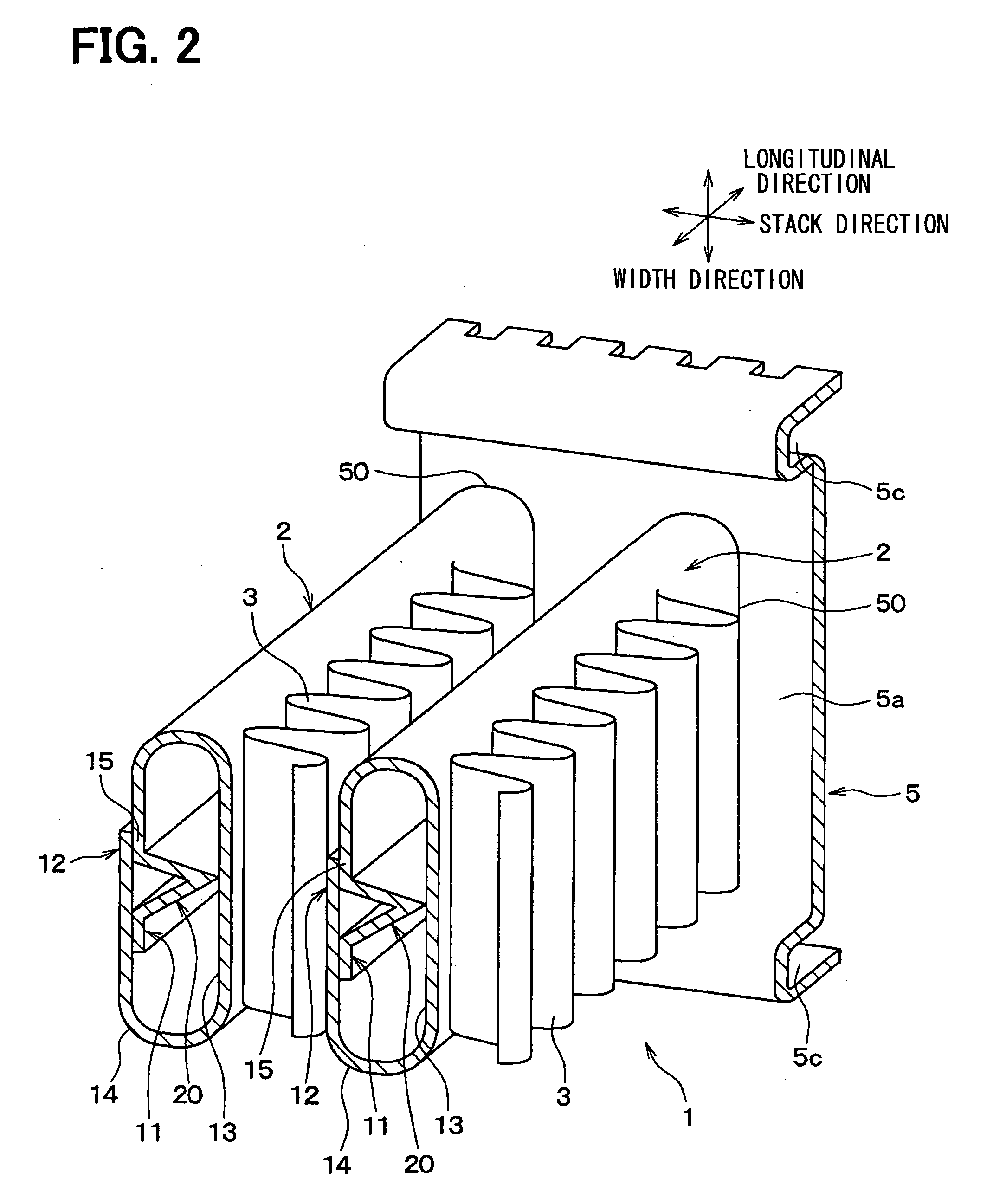
[0027]An embodiment of the present invention will be now described with reference to FIGS. 1 to 4H. In this embodiment, a tube 2 is typically used for a heat exchanger such as a radiator 1 in which engine coolant (thermal medium, fluid) is heat-exchanged with air. FIG. 1 shows an example of the radiator 1, and FIG. 2 shows tubes 2, fins 3 and a core plate 5a in a part of the radiator 1.

[0028]In the radiator 1 of FIG. 1, engine coolant flows in the tubes 2 which are stacked in a tube stack direction (stack direction). The tube 2 is a flat tube having an elliptic cross section, and each tube 2 is arranged such that a larger-diameter direction of the elliptic cross section of the tube 2 corresponds to the flow direction of air passing through the radiator 1. In the radiator 2, a plurality of the flat tubes 2 are stacked in the stack direction that corresponds to the top-bottom direction of FIG. 1. The flat tubes 2 are arranged parallel to each other, and each of the flat tubes 2 extend...


PUM

PropertyMeasurementUnit
Lengthaaaaaaaaaa
Widthaaaaaaaaaa

Abstract

A tube for a heat exchanger is constructed of a single plate having one end portion and the other end portion in a width direction perpendicular to a tube longitudinal direction. The single plate having opposite first and second wall surfaces is bent to have a protruding portion at a position adjacent to the one end portion in the width direction and a contact portion adjacent to the protruding portion in the width direction. The protruding portion is configured to continuously extend in the longitudinal direction and to have a protruding tip on a side of the first wall surface, and the protruding tip contacts the first wall surface of a portion along the longitudinal direction. The second wall surface at the one end portion and the contact portion contacts the first wall surface at the other end portion and a position near the other end portion, respectively.

Description

CROSS REFERENCE TO RELATED APPLICATION[0001]This application is based on Japanese Patent Application No. 2007-97417 filed on Apr. 3, 2007, the contents of which are incorporated herein by reference in its entirety.BACKGROUND OF THE INVENTION[0002]1. Field of the Invention[0003]The present invention relates to a tube for a heat exchanger and a method of manufacturing a tube, in which a fluid for a heat exchange flows. The heat exchanger can be suitably used as a radiator for a vehicle, for example.[0004]2. Description of the Related Art[0005]In a vehicle having an internal combustion engine, a heat exchanger such as a radiator for cooling engine coolant of the internal combustion engine is generally provided. In the heat exchanger, a plurality of tubes in which the coolant flows are arranged so that heat exchange is performed between air passing through the heat exchanger and the coolant flowing in the tubes, thereby cooling the coolant.[0006]For example, JP-A-10-47875 proposes a tub...

Claims


Application Information

Patent Timeline
IPC IPC(8): F28D1/04F28F1/00B21D53/06
CPCB21C37/155B21D53/06F28D1/0391F28D1/05383Y10T29/49377F28F1/022F28F2275/04Y10T29/49391F28D2021/0094
Inventor ITOH, TOMOHIRONAGAI, TAKAYUKI
Owner DENSO CORP
Learn More