Passive entry side door latch release system

a technology of latch release system and passive entry, which is applied in the direction of gearing, mechanical control devices, instruments, etc., can solve the problems of high space and current demands of motors, high operating speed and component complexity, and difficult to meet in vehicle applications

Inactive Publication Date: 2008-10-16
FORD GLOBAL TECH LLC
View PDF13 Cites 37 Cited by
  • Summary
  • Abstract
  • Description
  • Claims
  • Application Information

AI Technical Summary

Benefits of technology

[0013]The invention further provides a vehicle passive entry side door latch release system engageable with a release cable connected a door latch. The door latch release system may include a movable linkage assembly engageable with the release cable, and a motor including an output shaft having a first gear engaged with a second gear affixed to or formed with a third gear engaged with one or more ratcheting pawls engaged with internal gear teeth of a ring gear rotatably affixed to a coil spring, with the ring gear including external teeth engageable with a rack affixed to or formed with the linkage assembly to move the release cable to unlatch the door latch. Operation of the motor in a first motor rotary direction may drive the first, second and third gears in a first gear rotary direction to rotatably compressibly engage the pawl against the internal gear teeth of the ring gear to rotate the ring gear in the first gear rotary direction to energize the coil spring, and operation of the motor in a second opposite motor rotary direction may drive the first, second and third gears in a second opposite gear rotary direction to rotatably disengage the pawl from the internal gear teeth of the ring gear to allow stored energy in the coil spring to drive the ratcheting gearwheel in the second opposite gear rotary direction and to thereby drive the rack to move the release cable to unlatch the door latch.

Problems solved by technology

While the Rathmann passive latch release system decreases current demand for operation, this is at the expense of operation speed and component complexity.
Other systems, while able to operate a door latch within 50 ms, require motors with high space and current demands that are difficult to meet in vehicle applications.

Method used


Image

  • Passive entry side door latch release system
  • Passive entry side door latch release system
  • Passive entry side door latch release system

Examples


Embodiment Construction

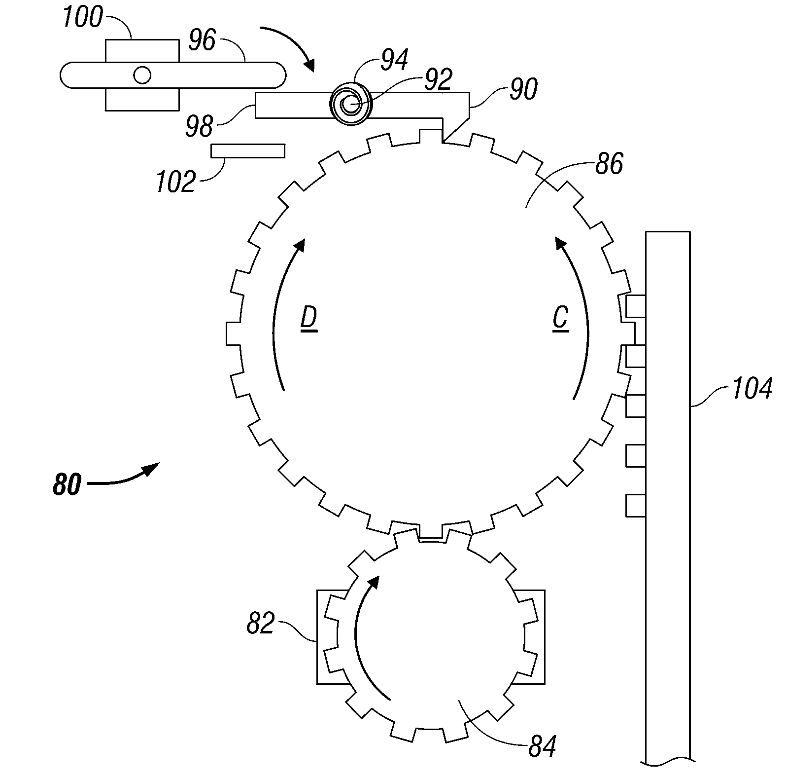
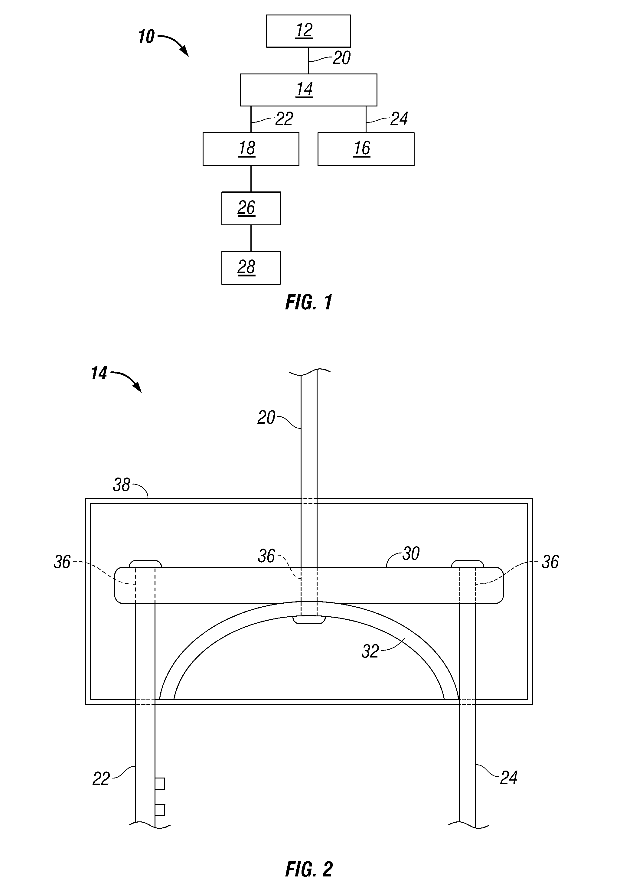
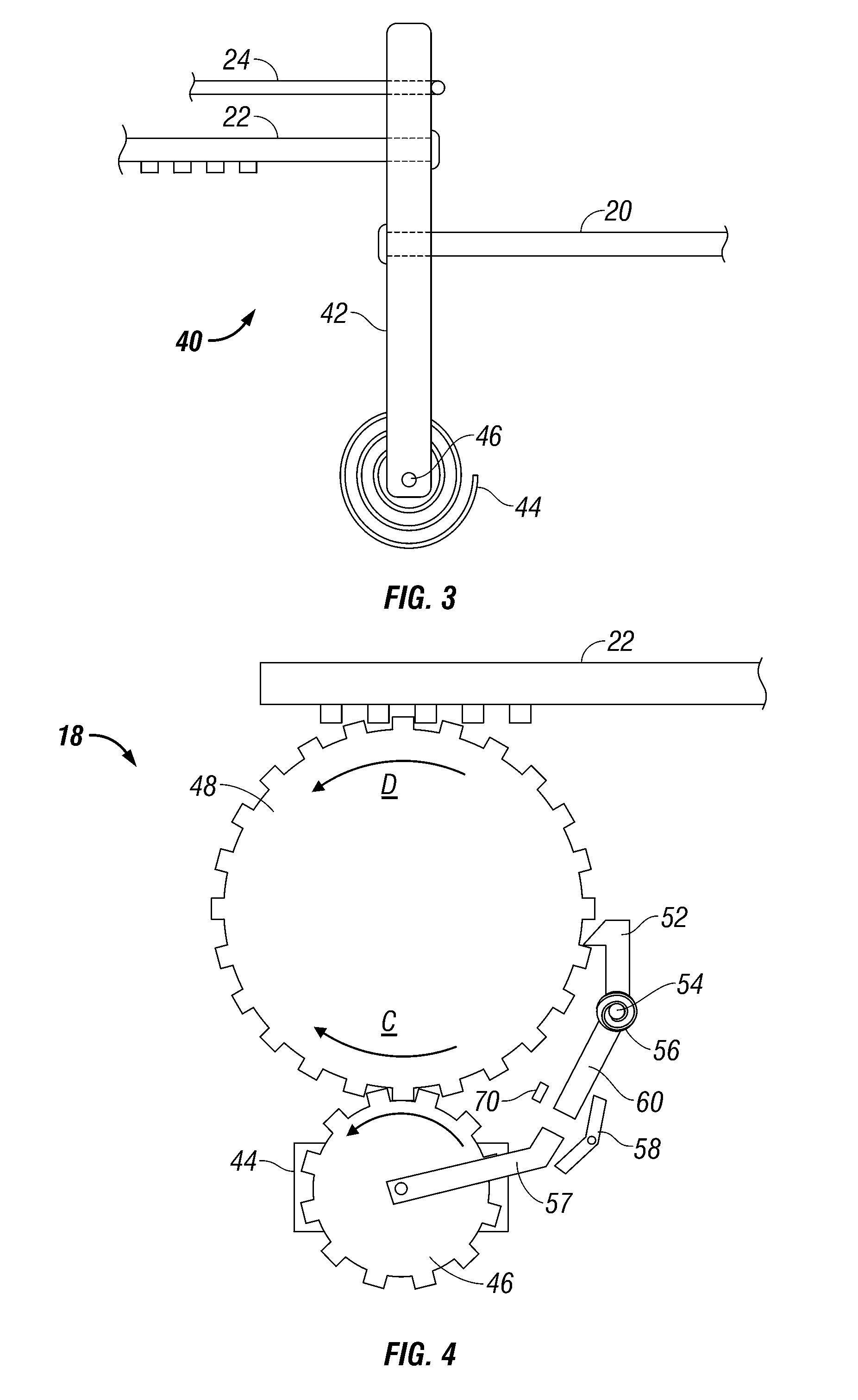
[0025]Referring now to the drawings wherein like reference numerals designate corresponding parts throughout the several views, FIG. 1 is a block diagram illustrative of a vehicle door latch release system according to the present invention, FIGS. 2 and 3 illustrate various embodiments of a movable linkage usable with the door latch release system of FIG. 1, and FIGS. 3-8 illustrate various embodiments of a cable release mechanism for use in the above-mentioned door latch release system.

[0026]As is known in the art, a conventional vehicle door latch release system generally includes an inside door handle connected to a door release latch by means of a release cable, and further includes an outside door handle connected to the door release latch by means of a latch rod. As is also known in the art, in order to open a conventional vehicle door from the outside, the door must first be unlocked and thereafter opened by, for example, the outside door handle. Further, in order to open a c...


PUM


Abstract

A vehicle passive entry side door latch release system engageable with a release cable connected a door latch includes a moveable linkage assembly engageable with the cable, and a motor including an output shaft engaged with a tensioning gear for driving a ratcheting gearwheel rotatably affixed to a coil spring, with the gearwheel including external teeth engageable with a rack affixed to the linkage to move the cable to unlatch the door latch. A pivotable ratcheting pawl may be engageable with the gearwheel to allow or prevent rotation of the gearwheel. Operation of the motor may drive the gear to drive the gearwheel in a rotary direction to energize the spring, and disengagement of the pawl from the gearwheel may allow stored energy in the spring to drive the gearwheel in an opposite rotary direction to thereby drive the rack to move the cable to unlatch the door latch.

Description

BACKGROUND OF INVENTION[0001]a. Field of Invention[0002]The invention relates generally to vehicle door latch release systems, and, more particularly, to a vehicle passive entry side door latch release system that can operate with existing door latch assemblies.[0003]b. Description of Related Art[0004]In recent years, automatic vehicle door latch release systems have become increasingly popular and are now available in a variety of new vehicles. Such door latch release systems normally operate by sending an electrical signal to a latch release unit when an operator either pulls an outside door handle, depresses an actuation switch underneath or adjacent the handle, or otherwise approaches the vehicle with a remote access unit. Once the outside handle is pulled or otherwise actuated, the latch release unit must release the latch or otherwise unlock the door within 50 ms or less to enable seamless operation of the latch release (or unlocking) and door opening functions.[0005]More spec...

Claims


Application Information

Patent Timeline
Patent Type & Authority Applications(United States)
IPC IPC(8): E05B65/20
CPCE05B15/0046E05B77/30E05B81/14Y10T74/1967E05B85/01E05B79/20Y10T74/20654E05B81/25Y10T292/1082
Inventor PAPANIKOLAOU, KOSTALOSCHIAVO, JAMESKRISHNAN, VENKYMERIDETH, MARCUS EDWARDPATEL, BHUPENDRA
Owner FORD GLOBAL TECH LLC
Why Eureka
Try Eureka