Intelligent door restraint

a technology of intelligent restraints and doors, applied in the direction of programmed manipulators, multi-purpose tools, constructions, etc., can solve the problems of inability to fully automatic door control, high cost, and inability to use line power with limited or lacking facilities for close coupling backup, etc., to improve control capability, improve performance, and cost-effective manufacture

Active Publication Date: 2012-07-24
HOFFBERG STEVEN M
View PDF801 Cites 136 Cited by
  • Summary
  • Abstract
  • Description
  • Claims
  • Application Information

AI Technical Summary

Benefits of technology

[0014]A further aspect of the invention provides an automatic or semiautomatic door control which is energy and space efficient, low cost, and which is readily installed without requiring permanent line wiring, while providing the benefits of an electronic control. The control therefore derives operational energy from manually initiated door movement, which is extracted and later employed to operate the control, close the door, or both.
[0017]The sensor and control system typically requires a power source, which may be a battery, solar power, wired power, an energy draw from the door opening, or the like. In many instances, the control will be capable of operation at low power draw, and therefore battery power for the control will be possible. The use of a battery for powering the electronic control allows a reliable power source independent of door operation. On the other hand, powering large or power intensive actuators with a battery will likely result in short operating life and frequent service to replace the battery. Therefore, it is preferred that any power intensive actuators draw energy from the door operation. In low duty operation environments, such as homes or some offices and closets, battery power is a feasible option for actuator power, especially lithium batteries.
[0020]In a preferred design, a door closing mechanism includes a hydraulic cylinder damper coupled with a spring, acting together to slowly close the door. According to the present invention, a controllable valve is provided to selectively block flow of hydraulic fluid, halting the closure of the door. This valve is, for example, a latching solenoid actuator (i.e., drawing power only when switching states) acting on a piston having a cross-drilled hole. In one position, fluid flows through the hole. In the other position, the hole is not aligned with corresponding flow passages, and no flow occurs. As can be seen, the power required by the system is typically the power to operate the electronic control, the power required to operate the sensor, and the power require to operate the actuator. Assuming the door is operated 4 times per day over the course of a year, there are less than 1,600 cycles of operation. If the system has a quiescent draw of 100 μA, and an operating draw of 1 A for 2 seconds per closure, then the total power for operation over a year will be less than about 2 AH (0.875 AH quiescent plus 0.811 AH active). Therefore, under such use, a primary lithium battery could be employed to power the entire system, with an annual replacement cycle. On the other hand, as the duty cycle increases, the ability to reasonably provide a low maintenance reliable system running off battery power decreases, and power extraction systems become more cost efficient.
[0021]A sensor mounted on the door closing device detects whether there is traffic within the doorway. If there is traffic, the door is restrained. Since people are conditioned for dumb (i.e., non-intelligent) door closing devices, and will be tempted to manually hold the door, a visual indicator, such as a blinking light emitting diode (LED) is provided to alert users that the device is operational. When the door is opened, a magneto generator may be operated, which charges a supercapacitor or rechargeable battery. A set of primary back-up batteries may also be provided. Since the magneto operation will damp the opening of the door, the hydraulic cylinder is provided with an asymmetric flow pattern, such that there is little hydraulic damping during door opening, since this would be redundant and would consume power which could be efficiently used by the magneto.
[0026]In order to provide resilience against externally applied forces, a bypass or friction plate is provided to prevent damage to the closing device.
[0028]It is understood that the present invention therefore provides, according to a first embodiment, an improvement for a standard door closer in the manner of an intelligent control, which, for example, may be retrofitted to existing door closers or form the basis for an improved design. In a second embodiment, an electrical system replaces the traditional hydraulic system to provide improved performance, enhanced control capability, and potentially more cost effective manufacture.

Problems solved by technology

Modern designs also include fully automatic door controls, which are expensive, and typically require continuous availability of power.
These systems are almost universally electrically powered, and employ line power with limited or lacking facilities for closely coupled backup.
Due to the damper in the door, a typical symmetric damping function, and a requirement to arm the device while opening the door, opening a door having an automatic door closing device involves application of a significant force.
This often results in significant delays and bottlenecks, since the person holding the door open often must stand in the door passage, applying a force, or stand in a contorted position to avoid being in the doorway.

Method used


Image

  • Intelligent door restraint
  • Intelligent door restraint
  • Intelligent door restraint

Examples


first embodiment

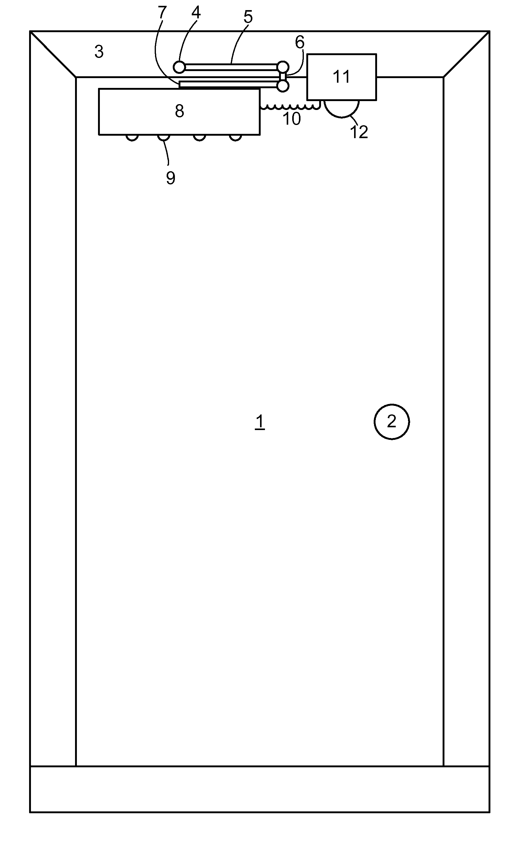
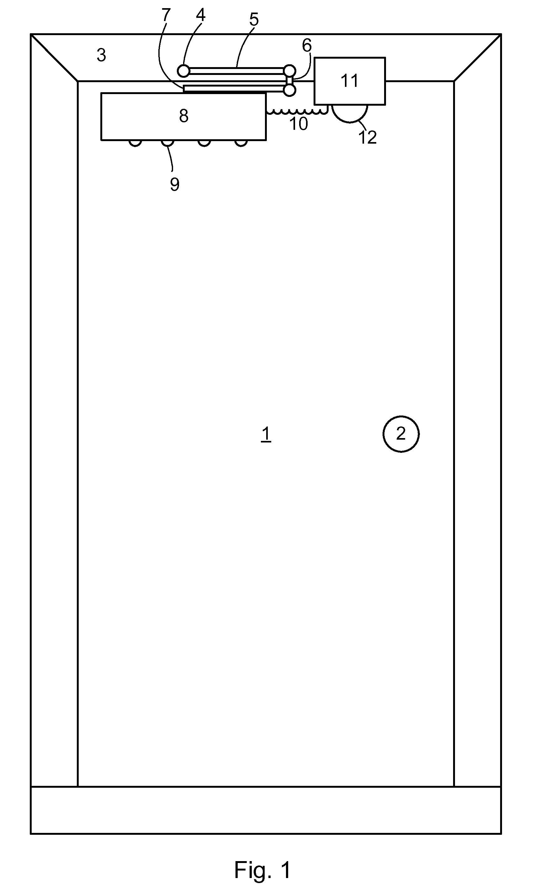
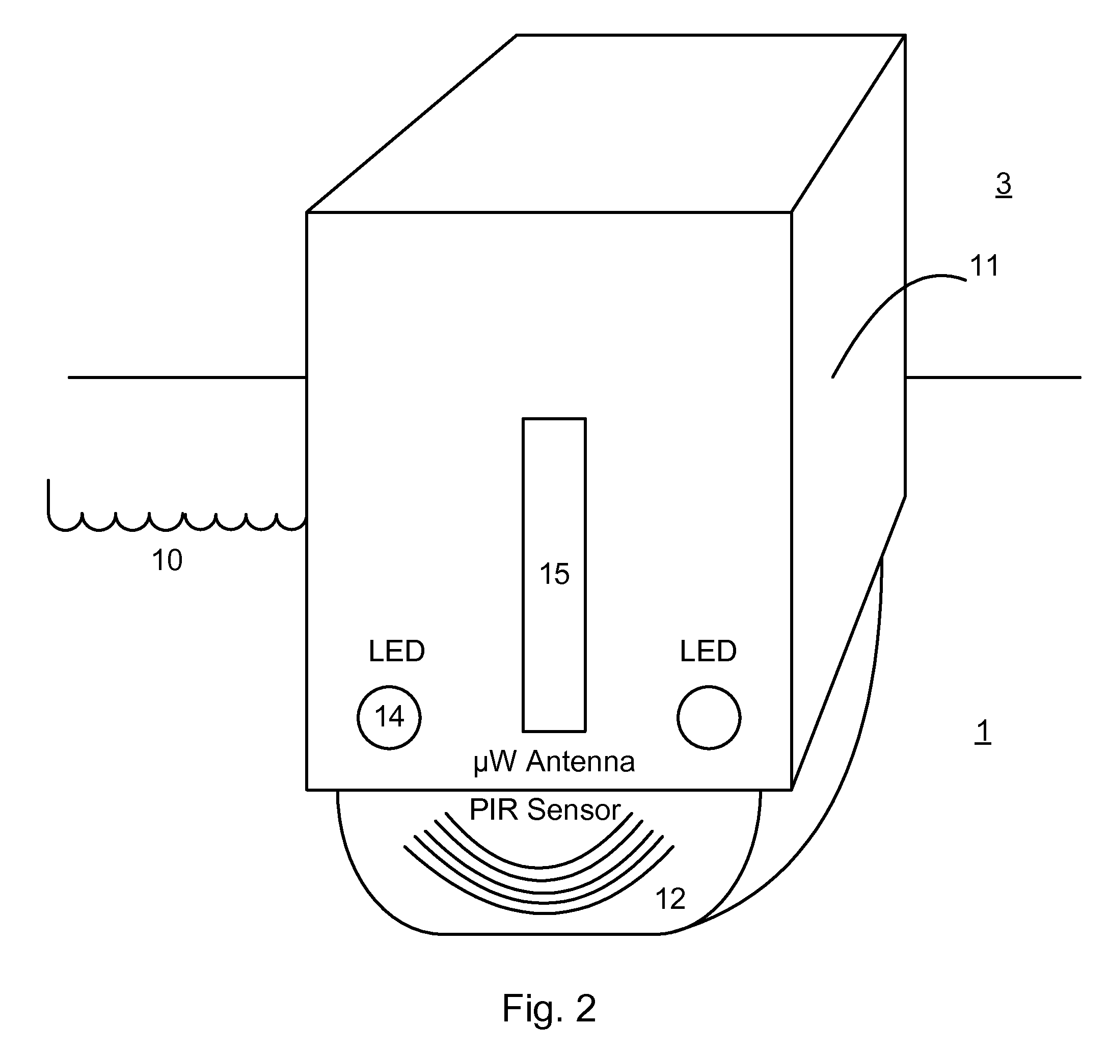
[0075]Examples of this intelligence include object sensing in a doorway, fire or smoke detection (and therefore door closure and / or alarm), remote activation, room occupancy sensing, and the like. In a first embodiment, a spring biased solenoid actuator is linked to a needle which controls flow through a restricting orifice 201, 202. The control 210 holds the actuator 201, 202 in the active and therefore hold-open state for so long as an object is in the doorway, or other condition exists for which the door should be held open. This method is fail safe, since a battery failure would result in default hydraulic door closure. A control 210 failure which activates the solenoid actuator 201, 202 would likely drain the battery 211 over a few hours. Thus, a fire safety rating or special exemption may likely be obtained. Since power is required to maintain the solenoid actuator 201, 202 in an activated state, a magneto generator 204 driven by the door opening through gear 205 is preferred....

second embodiment

[0076]In a second embodiment, the actuator employs a latching armature. In this case, it is possible for the battery to fail with the unit held in the open position; therefore this embodiment generally includes a base bleed which causes the door to close within 1-5 minutes, and so provide a graceful and fail safe mode. This type of system may have lower battery drain than a system in which continuous power is required to restrain door closure.

third embodiment

[0077]In a third embodiment, shown in FIG. 12, a collapsible mechanical toggle linkage 220 is reset each time the door is opened by extension of a moveable member 221 within the door closer. See, U.S. Pat. No. 6,031,438, expressly incorporated herein by reference. The control 222 then generates a signal which activates a solenoid 223 which pulls an armature 224, which displaces a seer pin (not shown in FIG. 12) and collapses the toggle linkage 220 when the door closure is to be activated, which allows the normal hydraulic door closure mechanism 225 to operate. In this case, only a single actuator pulse is required to close the door. On the other hand, this acts as an automatic hold-open, and thus would likely be applicable especially for non-fire safety rated operation.

[0078]As can be seen, the control 222 may receive, for example, an external signal to trigger door closure, such as a fire alarm or a timer. A manual reset may also be provided to trigger the door closure in case of c...


PUM


Abstract

A method for controlling a door, comprising the steps of storing energy during a manual opening of a door, sensing an object within a doorway, selectively applying a force derived from the stored energy, to close the door, based on the sensing of an object in the doorway. The closure is preferably controlled by an electronic control. A door closing device comprising an energy storage device for storing energy during door opening and releasing the stored energy to subsequently close the door, a damping system for damping a closure of the door, a sensor for detecting an object within a doorway, having an output, a controllable device for selectively restraining the energy storage device from closing the door, and a control system for controlling the controllable device based on the output.

Description

CROSS REFERENCE TO RELATED APPLICATIONS[0001]The present application is a continuation of U.S. patent application Ser. No. 10 / 196,684 filed Jul. 15, 2002 now abandoned and claims benefit of priority from U.S. Provisional Patent Application Ser. No. 60 / 305,130 filed Jul. 13, 2001.FIELD OF THE INVENTION[0002]The present invention relates to the field of automatic door closing devices, and in particular devices that hold a door open to allow people to pass through.BACKGROUND OF THE INVENTION[0003]Door closing devices are well known, and have existed for centuries. A simple string, pulley and counterweigh is sufficient to close a door after opening. Modern designs incorporate hydraulic or pneumatic devices to moderate the closure rate.[0004]Modern designs also include fully automatic door controls, which are expensive, and typically require continuous availability of power. These systems are almost universally electrically powered, and employ line power with limited or lacking facilitie...

Claims


Application Information

Patent Timeline
Patent Type & Authority Patents(United States)
IPC IPC(8): E05F3/00
CPCE05F3/102E05F15/73E05Y2900/132E05Y2201/43E05Y2800/67Y10T16/62Y10T16/27Y10T16/276Y10T16/625E05F15/42B25J9/1694E05F3/10E05F3/222
Inventor HOFFBERG, STEVEN M.
Owner HOFFBERG STEVEN M
Why Eureka
Try Eureka