Broach handle for minimally invasive hip replacement surgery

a hip replacement and minimally invasive technology, applied in the field of preparation of the intramedullary canal of the femur, can solve the problems of joint instability and pain, weakening and deformation of the bone cavity, and serious problems for the patien

Inactive Publication Date: 2008-10-16
ORTHOGROUP
View PDF35 Cites 82 Cited by
  • Summary
  • Abstract
  • Description
  • Claims
  • Application Information

AI Technical Summary

Benefits of technology

[0020]whereby manipulation of the proximal end o...

Problems solved by technology

An improper fit of the femoral prosthesis within the cavity may lead to micro-rotation of the stem relative to the femur and unstable fixation, which may cause the bone cavity to weaken and deform over time.
This can present serious problems for the patien...

Method used


Image

  • Broach handle for minimally invasive hip replacement surgery
  • Broach handle for minimally invasive hip replacement surgery
  • Broach handle for minimally invasive hip replacement surgery

Examples


Embodiment Construction

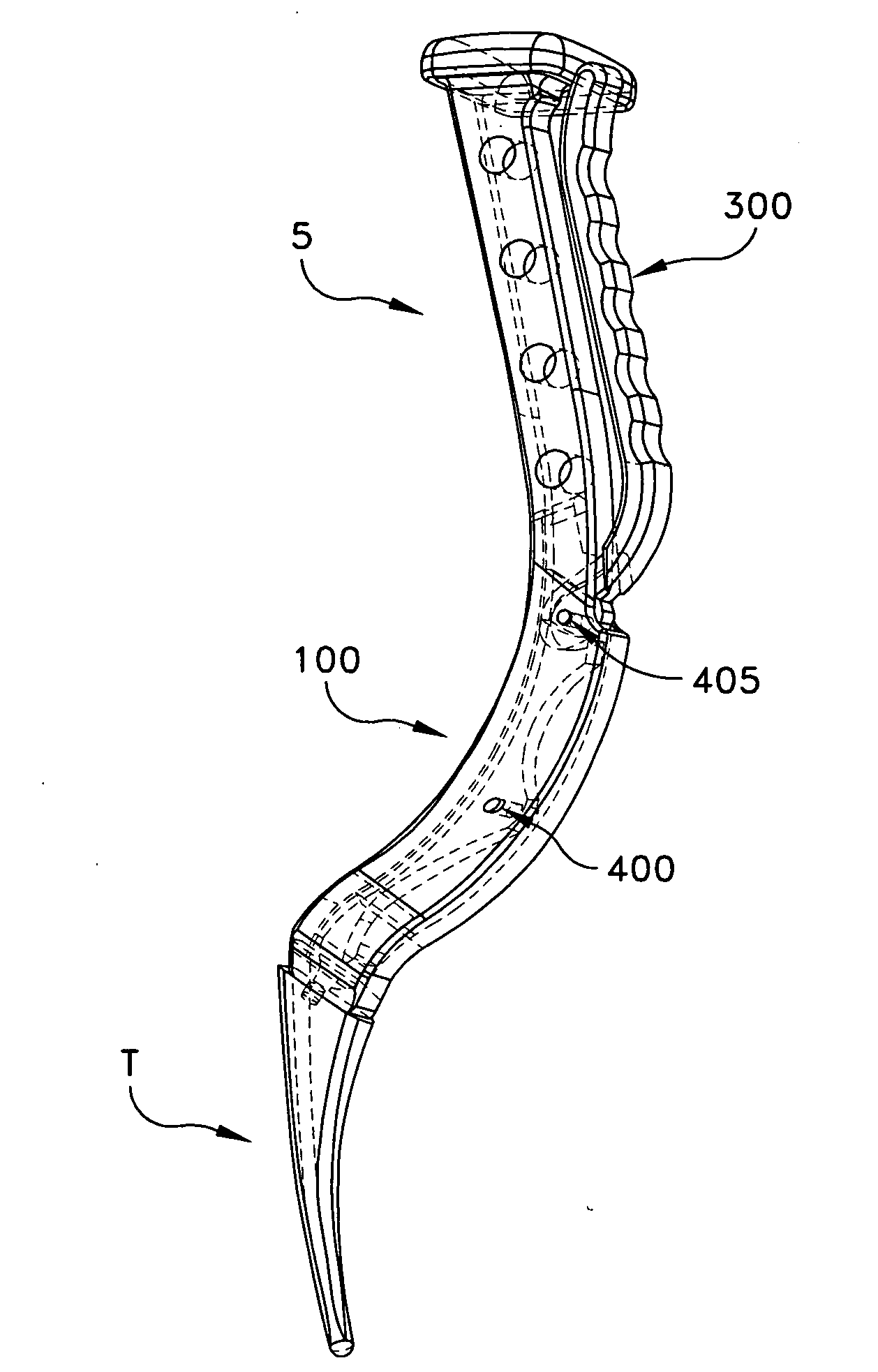
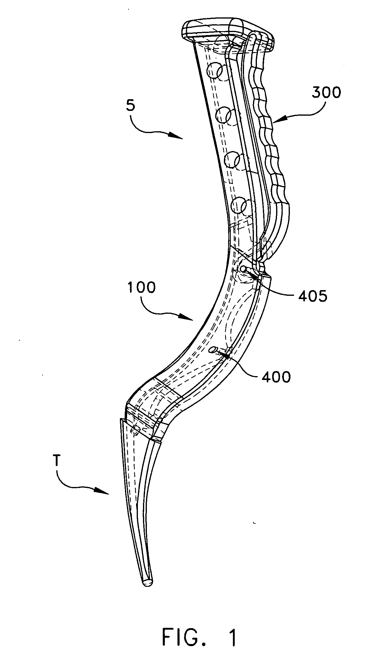
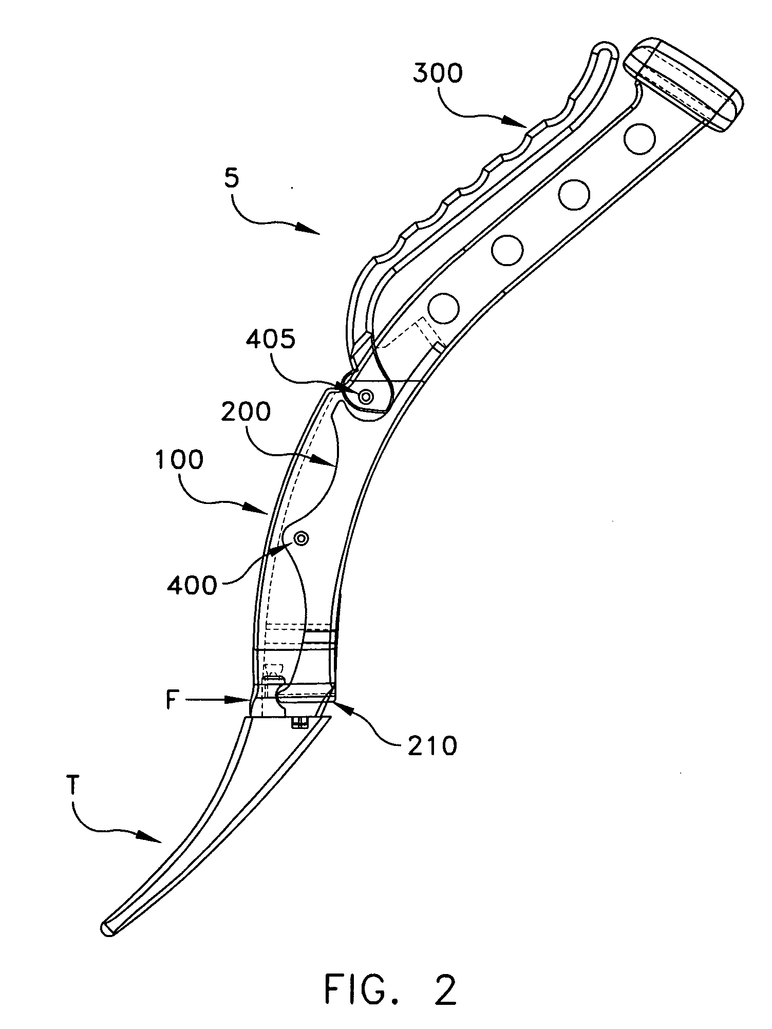
[0029]Looking now at FIGS. 1-3, in one preferred form of the present invention, there is provided a novel broach handle 5 for use in manipulating a conventional broach T. Broach handle 5 generally comprises a body 100, a linkage 200 and a lever 300.

[0030]Broach T may be any broach compatible with the present invention. Looking now at FIGS. 1-3 and 4-6, broach T is generally characterized by a working end W and a connector C. Connector C is generally characterized by a bore B and a finger F including a recess R.

[0031]Body 100 is shown in FIGS. 1-3 and 7-10. Body 100 has a proximal end 105 and a distal end 110. As seen in FIG. 8, distal end 110 is laterally offset from proximal end 105. In addition, as seen in FIG. 10, distal end 110 is longitudinally offset from proximal end 105. Distal end 110 includes a finger 115 for disposition in bore B of broach T, and a recess 120 for receiving finger F of broach T. Proximal end 105 includes a strike plate 125 terminating in a strike surface 1...


PUM


Abstract

A broach handle for attachment to a broach comprising a distal working end and a proximal connector end, the proximal connector end comprising a bore extending distally into the broach, and a finger comprising a recess and extending proximally away from the broach, the broach handle comprising: a body having a distal end and a proximal end, the distal end being longitudinally and laterally offset from the proximal end and comprising a finger for seating in the bore of the broach and a bore for receiving the finger of the broach; a linkage connected to the body and comprising a finger for selective disposition in the recess of the finger of the broach; and a lever connected to the body and arranged to manipulate the proximal end of the linkage so that manipulation of the proximal end of the lever can lock and unlock a broach to the handle.

Description

REFERENCE TO PENDING PRIOR PATENT APPLICATION[0001]This patent application claims benefit of pending prior U.S. Provisional Patent Application Ser. No. 60 / 860,062, filed Nov. 20, 2006 by Henry H. Fletcher for UNIVERSAL BROACH HANDLE (Attorney's Docket No. ORTHO-1 PROV), which patent application is hereby incorporated herein by reference.FIELD OF THE INVENTION[0002]This invention relates to the preparation of a bone for an implant in general, and more particularly to the preparation of the intramedullary canal of a femur for a minimally invasive total hip replacement.BACKGROUND OF THE INVENTION[0003]Joint replacement surgery seeks to replace portions of a joint with prosthetic components so as to provide long-lasting function and pain-free mobility.[0004]More particularly, in the case of a total hip replacement, the head of the femur is removed and replaced with a prosthetic femoral component, and the socket of the acetabulum is replaced by a prosthetic acetabular component, whereby ...

Claims


Application Information

Patent Timeline
IPC IPC(8): A61B17/00
CPCA61B17/1659A61B17/1668A61B2017/0046
Inventor FLETCHER, HENRY H.
Owner ORTHOGROUP
Why Eureka
Try Eureka