Pneumatic connections for prosthetic socket

a technology of prosthetic sockets and connectors, which is applied in the field of pneumatic connectors for prosthetic sockets, can solve the problems of swelling into the end of the socket, and affecting the function of the prosthesis

Active Publication Date: 2008-10-30
OTTO BOCK HEALTHCARE IP GMBH & CO KG
View PDF8 Cites 31 Cited by
  • Summary
  • Abstract
  • Description
  • Claims
  • Application Information

AI Technical Summary

Benefits of technology

[0018]Accordingly, there is a continuing need for flexible pneumatic connectors for use with artificial limbs by mounting on prosthetic sockets, which are capable of withstanding impact without dislodging from the socket and provide a connection between the interior of the socket and a pressure source. The artificial limb includes a prosthetic socket having an open-ended socket wall with an inner surface and an outer surface, into which a residual limb may be inserted. The socket forms, when the residual limb is inserted, a sealed interior wherein a positive or negative pressure may be generated through a hole in the wall of the socket when connected to a pressure source. The present invention provides a connector for use with this artificial limb. The connector fluidly connects the sealed interior of the socket with the pressure source when the connector is mounted to the socket at the hole and withstands impact without dislodging from the socket.

Problems solved by technology

These types of sockets caused a lot of shear force on the stump, as well as had pressure or restriction problems on the nerve bundles and vascular flow of fluid by way of the circumferential pressure effect of the socket on the limb.
This pressure effect could cause a swelling into the ends of the socket where an amputee may develop severe edema and draining nodules at the end of their stump.
However, problematic tissue configurations, such as bony prominences, required special consideration, such as the addition of soft or pliable materials to be put into the socket.
Some of the problems with these positive pressure systems are that they use a very specific pressure at specific locations resulting in the creation of atrophy and loss of tissue dramatically over these high pressure areas.
None of these systems employs positive pressure distributed over the total contact area between the residual limb and the artificial limb socket to accommodate volume changes within the socket.
This did not work particularly well because it would cause swelling of the residual limb into the chamber created by the negative draw of suspending the weight of the leg and being in a confined area.
This would lead to significant edema which would be severe enough to cause stump breakdown and drainage.
This loss of fluids causes the volume of the residual limb to decrease during the day.
These materials have a tendency to delaminate when drilled and, if the material is porous, then air can migrate through the material to form a leak path.
The disadvantage of using a metal elbow fitting is that the fitting is very rigid, fairly large and protrudes from the side of the socket.
If this fitting is bumped or jarred during the amputees daily activities, the stiff fitting transfers all of the impact load to the threads in the socket.
This can result in breakage of the threads and subsequent pneumatic leaks.

Method used


Image

  • Pneumatic connections for prosthetic socket
  • Pneumatic connections for prosthetic socket
  • Pneumatic connections for prosthetic socket

Examples


first embodiment

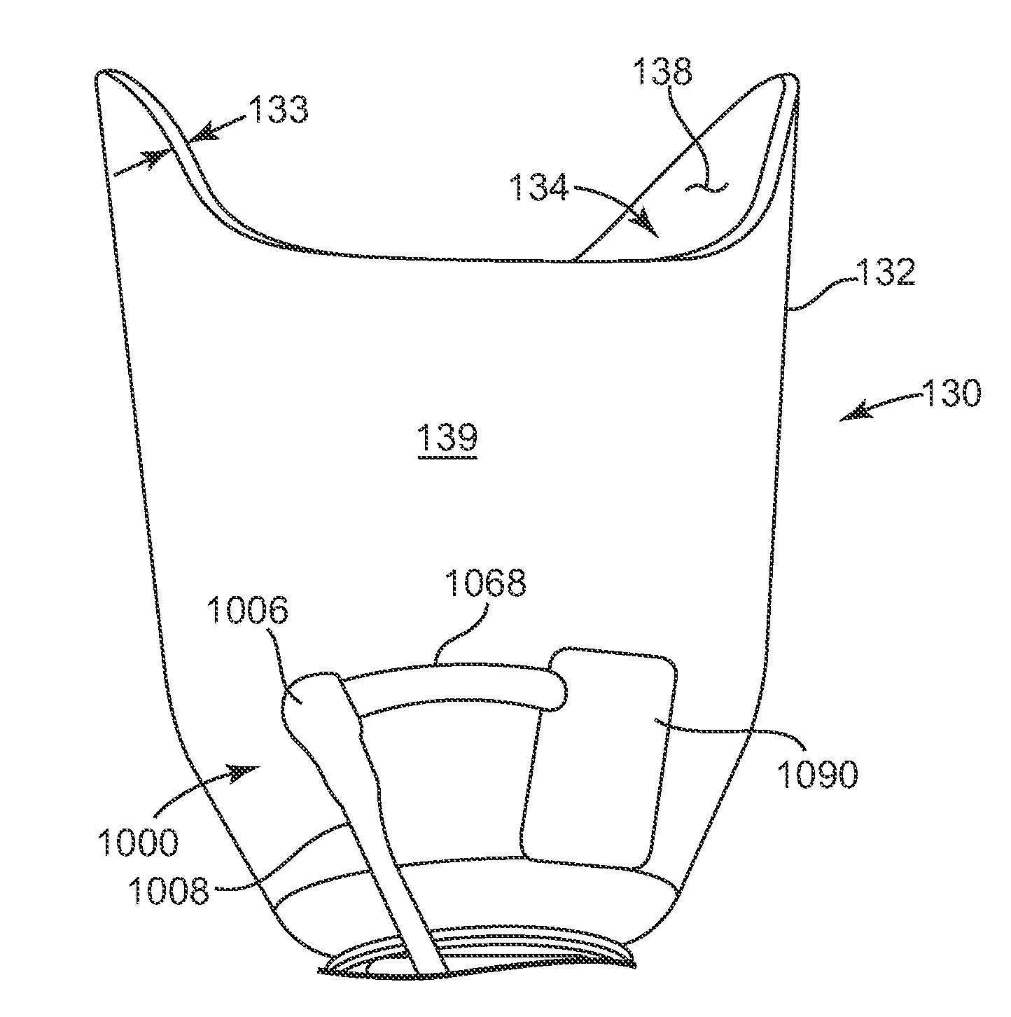
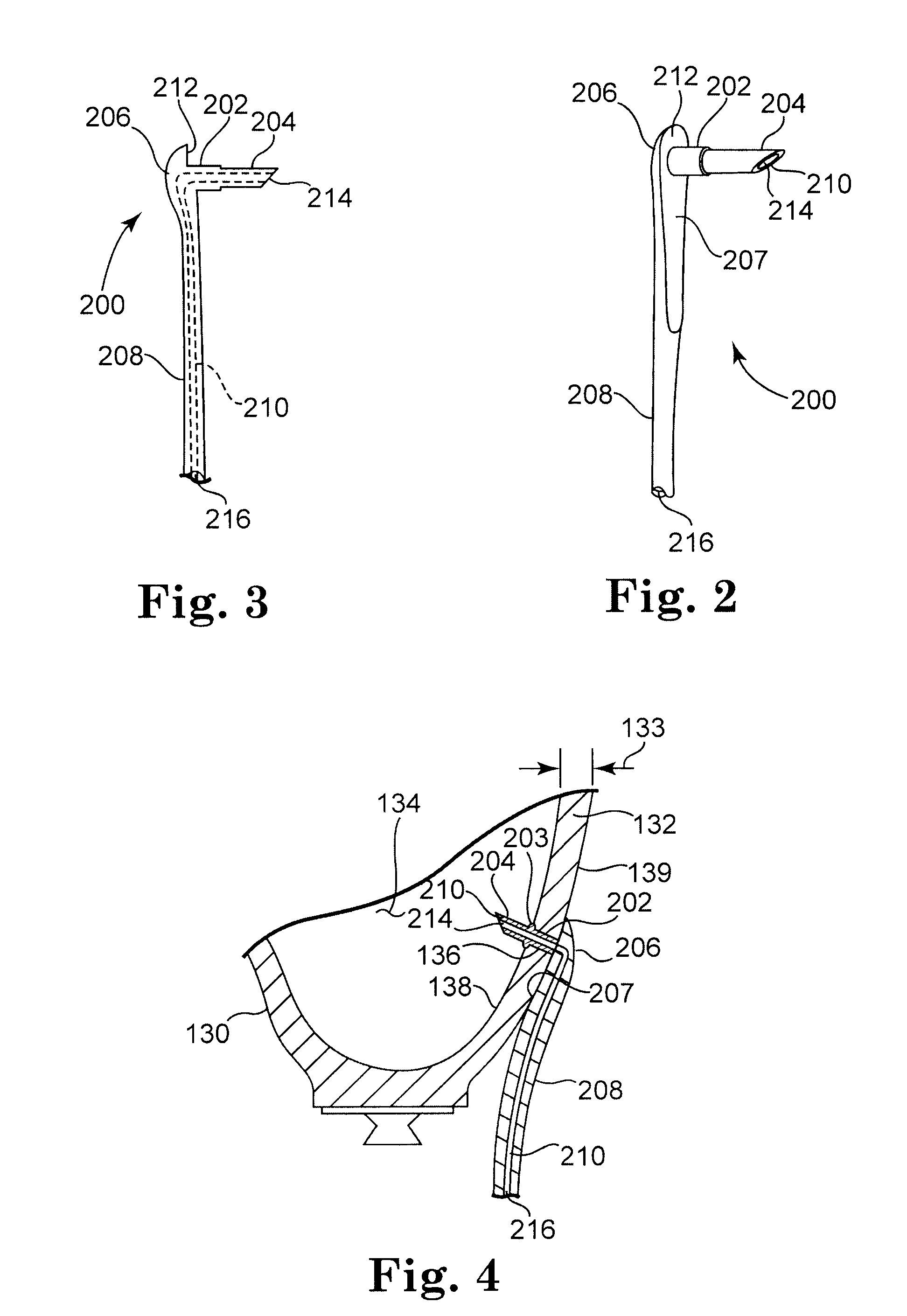
[0041]FIGS. 2 and 3 show a low profile flexible pneumatic connector 200 in accordance with the invention. Connector 200 is formed from a high strength elastomer or other suitable flexible material. Connector 200 includes elongated tubular section 208, flange 206, tubular head section 202, tubular insertion section 204, and lumen 210. Flange 206 is formed at one end of elongated tubular section 208 with tubular head section 202 extending from a portion of surface 212 on flange 206 and terminating as tubular insertion section 204. The outside diameter of tubular head section 202 is greater than the outside diameter of tubular insertion section 204. Lumen 210 extends the length of connector 200 between opening 214 of tubular insertion section 204 and opening 216 the other end of elongated tubular section 208.

[0042]FIG. 4 is a partial cross-sectional view of artificial limb socket 130 having connector 200 mounted through wall 132 of socket 130. Socket 130 includes socket wall 132 having...

second embodiment

[0045]FIGS. 5 and 6 show a low profile flexible pneumatic connector 300 in accordance with the invention. Connector 300 is formed from a high strength elastomer or other suitable flexible material. Connector 300 includes flange 306 having surfaces 312 and 313, tubular head section 302, elongated tubular section 308, and lumen 310. Flange 306 is formed at one end of tubular head section 302 having elongated tubular section 308 extending from the other end of tubular head section 302. Lumen 310 extends the length of connector 300 between opening 314 on surface 313 of flange 306 and opening 316 the other end of elongated tubular section 308. The outside diameter of tubular head section 302 is somewhat greater than the outside diameter of elongated tubular section 308.

[0046]FIG. 7 is a partial cross-sectional view of artificial limb socket 130 having connector 300 mounted through wall 132 of socket 130. In order to enable a snug and reasonably air-tight connection between connector 300 ...

third embodiment

[0048]FIG. 8 is a partial cross-sectional side view of a low profile flexible pneumatic connector 400 mounted through the wall 132 of artificial limb socket 130. Connector 400 is formed from a high strength elastomer or other suitable flexible material. Connector 400 includes flange 404 having surfaces 412 and 413, tubular head section 402, tubular bulbous section 420, elongated tubular section 408, and lumen 410. Tubular head section 402 includes flange 404 at one end, and tubular bulbous section 420 at the other end whereat tubular head section 402 transitions into elongated tubular section 408. The length of tubular head section 402 is equal to or slightly less than thickness 133 of socket wall 132, and yet it is sufficiently long so that tubular head section 402 extends within hole 136 to ensure a snug fit when surface 412 of flange 404 abuts against inner surface 138 of socket wall 132. As such, the combination of flange 404 and tubular bulbous section 420 aid in a snug connect...


PUM


Abstract

A connector for fluidly connecting the sealed interior of an artificial limb socket with a pressure source when the connector is mounted to the socket at a hole and an artificial limb including same. The connector includes a flexible elongated tubular section having a lumen, a flange coupled to one end of the elongated tubular section, the flange having a seal surface for sealingly abutting one of the socket wall surfaces around the hole, and a tubular portion adjacent to the flange and extending the lumen from the seal surface of the flange. Tubular portion has at least one section oversized relative to hole which provides a reasonable air-tight seal between the at least one section and an inner surface of the hole or the other of said socket wall surfaces around the hole and distant from the flange, when the tubular portion is received within the hole.

Description

[0001]This application claims the benefit under 35 U.S.C. 119(e) of U.S. 60 / 914,564, filed on Apr. 27, 2007, entitled PNEUMATIC CONNECTOR FOR PROSTHETIC SOCKET, which is hereby incorporated by reference in its entirety.TECHNICAL FIELD[0002]This invention relates to pneumatic connectors for prosthetic sockets, in particular, for fluidly connecting a pressure source to the socket interior.BACKGROUND[0003]An amputee is a person who has lost part of an extremity or limb such as a leg or arm, the remainder of which commonly may be termed as a residual limb. Residual limbs come in various sizes and shapes with respect to the stump. That is, most new amputations are either slightly bulbous or cylindrical in shape while older amputations that may have had a lot of atrophy are generally more conical in shape. Residual limbs may further be characterized by their various individual problems or configurations including the volume and shape of a stump and possible scar, skin graft, bony prominen...

Claims


Application Information

Patent Timeline
Patent Type & Authority Applications(United States)
IPC IPC(8): A61F2/72A61F2/60A61F2/80
CPCA61F2/68A61F2/80A61F2002/705A61F2002/742A61F2002/7655A61F2002/769A61F2002/802A61F2002/805A61F2002/807A61F2/742
Inventor STREET, GLENN M.MOSLER, LUDERFINLINSON, ROBERT EDWARDCLOVER, WILLIAM M.LAATSCH, ERIK
Owner OTTO BOCK HEALTHCARE IP GMBH & CO KG
Why Eureka
Try Eureka