Interchangeably manual or automatic ratchet wrench tool

a ratchet wrench and manual technology, applied in the direction of wrenches, power-driven tools, screwdrivers, etc., can solve the problem of limited operation efficiency

Inactive Publication Date: 2008-11-06
A INDAL +1
View PDF3 Cites 27 Cited by
  • Summary
  • Abstract
  • Description
  • Claims
  • Application Information

AI Technical Summary

Benefits of technology

[0012]The primary object of the present invention is to provide an interchangeably manual or automatic ratchet wrench tool that the user may couple an electric hand grip having a motor therein to the rear end of a stud member of a handle so as to urge a cartridge to rotate in an electric operation manner, or couple a manual hand grip to the rear end of the stud member of the handle so as to urge the cartridge to rotate in a manual operation manner, thereby achieving a multi-purpose operation.

Problems solved by technology

However, such a conventional tang and ratchet wrench with rotating disc operated direction change of drive and ratcheting can not be interchanged to operate in an electric operation mode, thus its operational efficiency is limited.

Method used


Image

  • Interchangeably manual or automatic ratchet wrench tool
  • Interchangeably manual or automatic ratchet wrench tool
  • Interchangeably manual or automatic ratchet wrench tool

Examples


Embodiment Construction

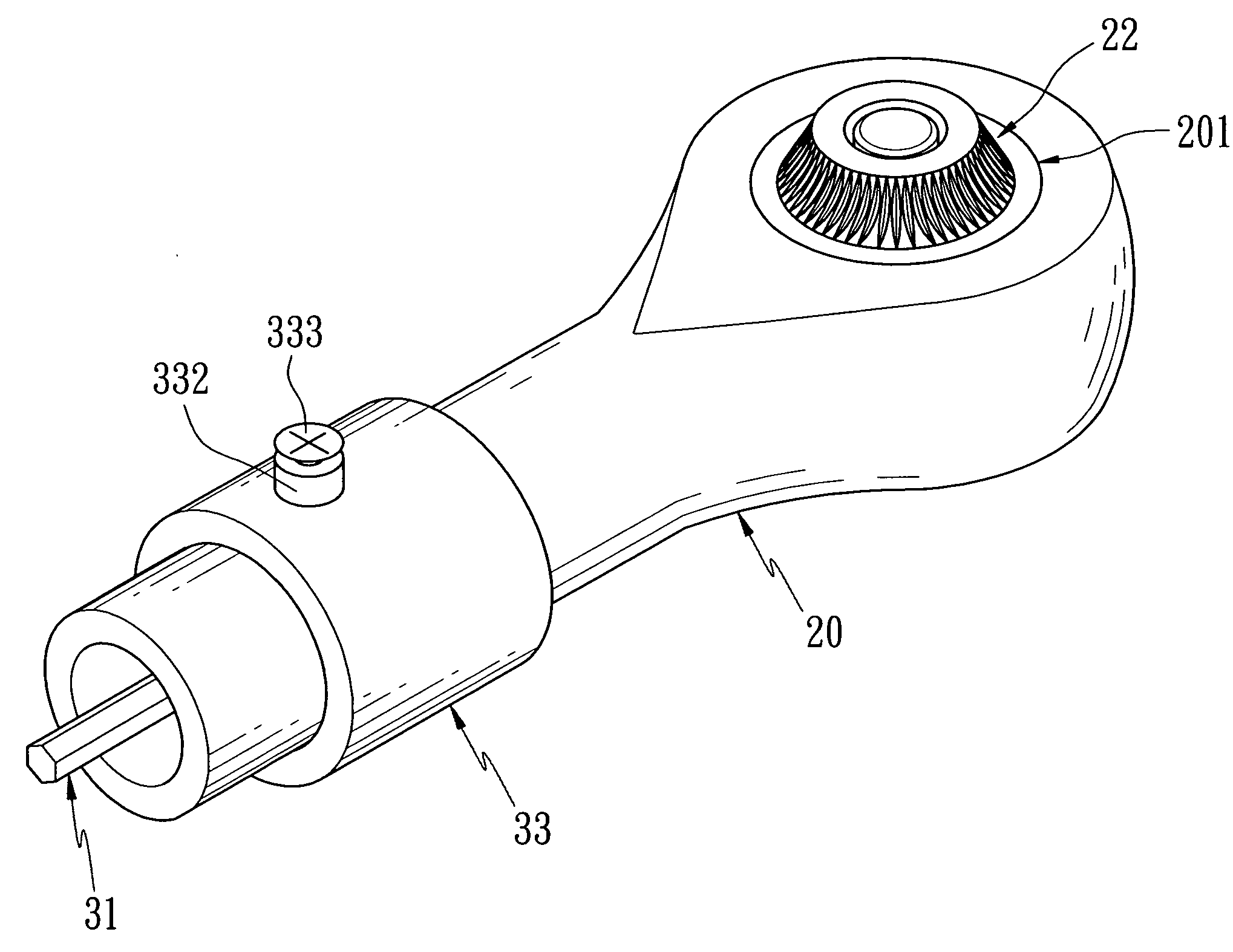
[0038]Referring to FIGS. 6-9, an interchangeably manual or automatic ratchet wrench tool in accordance with the present invention comprises a handle 20 including a chamber 201 defined in the head end thereof and having an internal gear 202 provided therearound, the chamber 201 further includes a lower peripheral shoulder 203 and an upper peripheral shoulder 204 disposed around the lower and upper portions of the internal shoulder 203 respectively, and includes a cartridge 21 received therein. Besides, the handle 20 also includes a longitudinal channel 205 arranged therethrough and communicating with the chamber 201. The cartridge 21 includes an actuation bar 211 attached to the bottom thereof for insertion into the lower peripheral shoulder 203, and includes two lateral cavities 212 and 213 defined thereon and having engaging walls 215 and 216 attached to the sides thereof respectively, and includes a longitudinally large-diametered bore 214 also fixed thereon and having a small-dia...


PUM


Abstract

The present invention relates to an interchangeably manual or automatic ratchet wrench that the user may couple an electric hand grip having a motor therein to the rear end of a stud member of a handle so as to urge a cartridge to rotate in an electric operation manner, or couple a manual hand grip to the rear end of the stud member of the handle so as to urge the cartridge to rotate in a manual operation manner, such that achieving a multi-purpose operation.

Description

BACKGROUND OF THE INVENTION[0001]1. Field of the Invention[0002]The present invention relates to an interchangeably manual or automatic ratchet wrench that can easily interchange its hand grip so as to have different operational modes.[0003]2. Description of the Prior Arts[0004]Referring to FIGS. 1-3, U.S. application Ser. No. 11 / 606,319 filed on Nov. 28, 2006, to Lin et al., discloses a conventional tang and ratchet wrench with rotating disc operated direction change of drive and ratcheting comprises an enclosed box portion 101 having driving teeth 102 around its interior surface provided in the wrench head integrally formed with a handle 10. A rotatable drive mechanism 11 is provided in the box portion 101. The drive mechanism 11 comprises first and second cavities 112, 113 thereon, a right surface 115 abutted the first cavity 112 and a left surface 116 abutted the second cavity 113, a channel 114 interconnected the first and second cavities 112 and 113, first pawl 14 having pawl ...

Claims


Application Information

Patent Timeline
Patent Type & Authority Applications(United States)
IPC IPC(8): B25B13/46
CPCB25B13/465B25B17/00B25B21/00B25G1/007
Inventor LIN, SHU-SUILI, WAN-CHUAN
Owner A INDAL
Why Eureka
Try Eureka