Device, System and Method of Retro-Modulating Safety Signs

a technology of safety signs and devices, applied in the field of road safety, can solve the problems of blinding another traffic participant and relatively low radiation intensity of led ligh

Inactive Publication Date: 2008-11-06
IRALINK
View PDF8 Cites 4 Cited by
  • Summary
  • Abstract
  • Description
  • Claims
  • Application Information

AI Technical Summary

Problems solved by technology

Moreover, the retroreflecting material may be attached to an object or site that may pose a danger to a user of the road.
However, using such high beams may also blind another traffic participant.
A striking disad...

Method used


Image

  • Device, System and Method of Retro-Modulating Safety Signs
  • Device, System and Method of Retro-Modulating Safety Signs
  • Device, System and Method of Retro-Modulating Safety Signs

Examples


Embodiment Construction

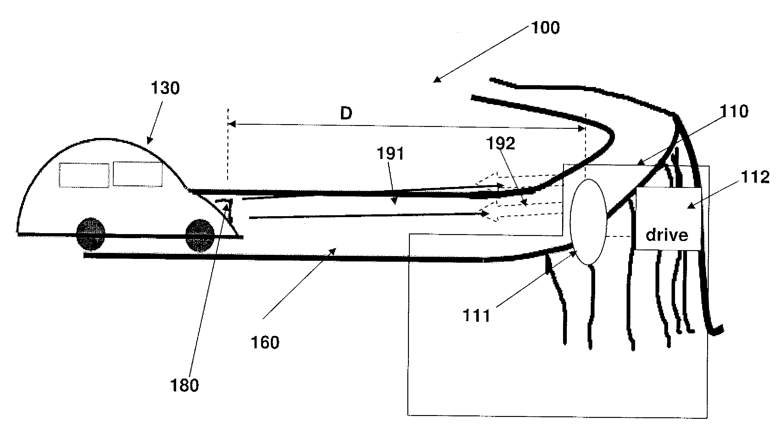
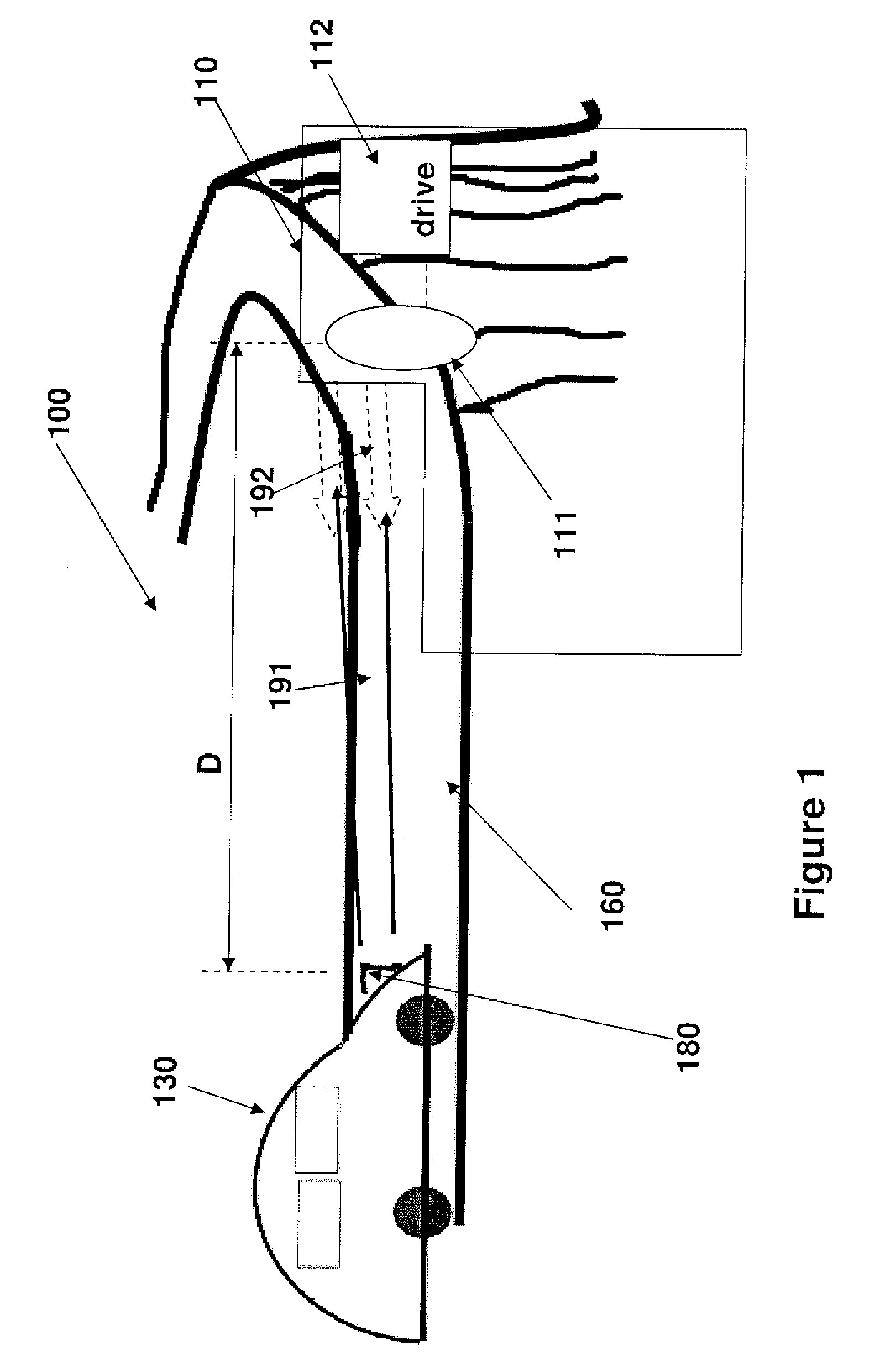
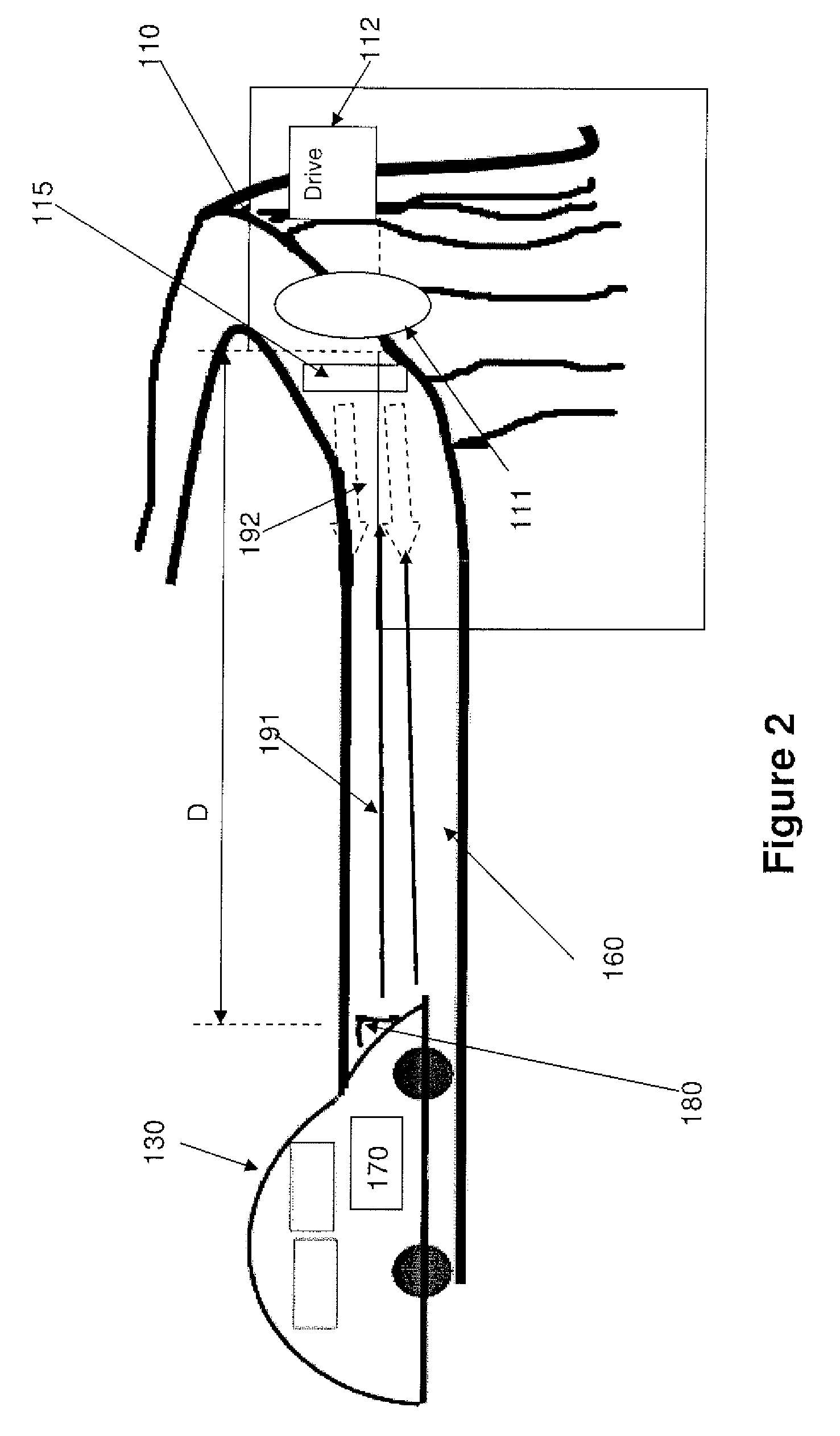
[0026]According to some demonstrative embodiments of the invention, a traffic safety system may be affiliated with an object to be seen from a distance and may be located within a traffic area.

[0027]In some embodiments, the traffic safety system may comprise a retroreflecting mechanism, enabling to switch between reflecting mode and non retroreflecting mode at certain frequency, thereby creating a flickering effect.

[0028]In some embodiments, the retroreflecting mechanism may operated in a retroreflective normally on default mode. The non-reflecting mode may include an absorbing mode, a transmissive mode and / or a dispersive mode.

[0029]In some embodiments, the switching operation may be accomplished by applying to the retroreflector a voltage above a certain threshold.

[0030]In some embodiments, the switching operation may be accomplished by modulating at a predetermined frequency the voltage applied to the retroreflector.

[0031]In some embodiments, the switching operation may be accomp...


PUM


Abstract

A traffic safety system may be affiliated with an object to be seen from a distance and may be located within a traffic area. The traffic safety system may comprise a retroreflecting mechanism, enabling to switch between reflecting mode and non retroreflecting mode at certain frequency, thereby creating a flickering effect.
In some embodiments, the retroreflecting mechanism may operated in a retroreflective normally on default mode. The non-reflecting mode may include an absorbing mode, a transmissive mode and/or a dispersive mode.

Description

FIELD OF INVENTION[0001]This application relates generally to the field of road safety and, more particularly, to retroreflecting materials or setups used for increasing road safety.BACKGROUND OF THE INVENTION[0002]A retroreflecting material reflects radiation such as light substantially back to the origin of the radiation, regardless of the radiation's angle of incident onto the retroreflecting material, as known in the art. The radiation source may be, for example, headlights of a motor vehicle.[0003]A traffic safety system may include such a retroreflecting material, whereby the retroreflecting material may be attached to or located nearby any object participating in road traffic such as a pedestrian, an animal, a bicycle driver, or any type of vehicle such as a bicycle, a tractor, a car, a truck and the like. Moreover, the retroreflecting material may be attached to an object or site that may pose a danger to a user of the road. Such a site or object may be, for example, a const...

Claims


Application Information

Patent Timeline
IPC IPC(8): G02B5/124
CPCE01F9/015G08G1/095E01F9/619
Inventor KARASIKOV, NIRTAMIR, DAVID
Owner IRALINK
Why Eureka
Try Eureka