Releasing Control Unit For a Residential Fire Protection System

a control unit and residential technology, applied in fire rescue, dental surgery, medical science, etc., can solve the problems of drying sprinkler system being slower to respond to fire conditions, unable to provide any indication of how to determine hydraulic demand, and water delivery time, etc., to facilitate detector 46 operation and facilitate water delivery

Active Publication Date: 2008-11-13
TYCO FIRE PRODS LP
View PDF28 Cites 55 Cited by
  • Summary
  • Abstract
  • Description
  • Claims
  • Application Information

AI Technical Summary

Benefits of technology

The technical effect of this patent is to provide a way to install fire detectors in relation to sprinklers to ensure they operate correctly without causing delays or damage during a fire outbreak. This involves placing detectors at specific locations based on their ability to monitor changes in temperatures caused by flames. By doing this, it allows for quicker detection and more efficient use of fire suppression equipment.

Problems solved by technology

The technical problem addressed in this patent text is the absence of effective guidance on how to design and install a dry type residual fire protection system in a home using standardized tools and methods. Existing national standards require specific hydraulic densities but do not allow for the use of different types of fire sprinklers beyond what they specify. Additionally, current regulations only describe minimal requirements for controlling the operation of individual sprinkers, while providing no instruction on monitoring and maintaining them.

Method used


Image

  • Releasing Control Unit For a Residential Fire Protection System
  • Releasing Control Unit For a Residential Fire Protection System
  • Releasing Control Unit For a Residential Fire Protection System

Examples


Embodiment Construction

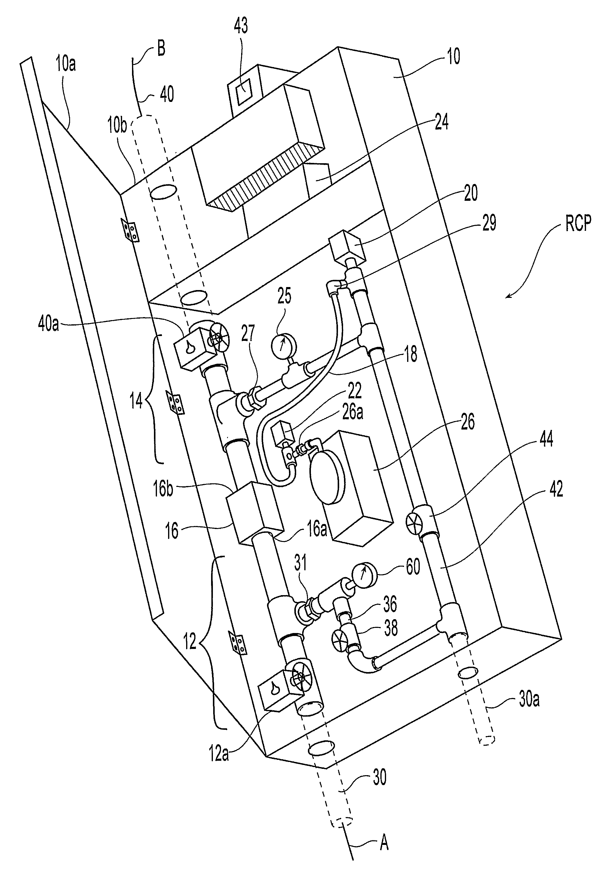
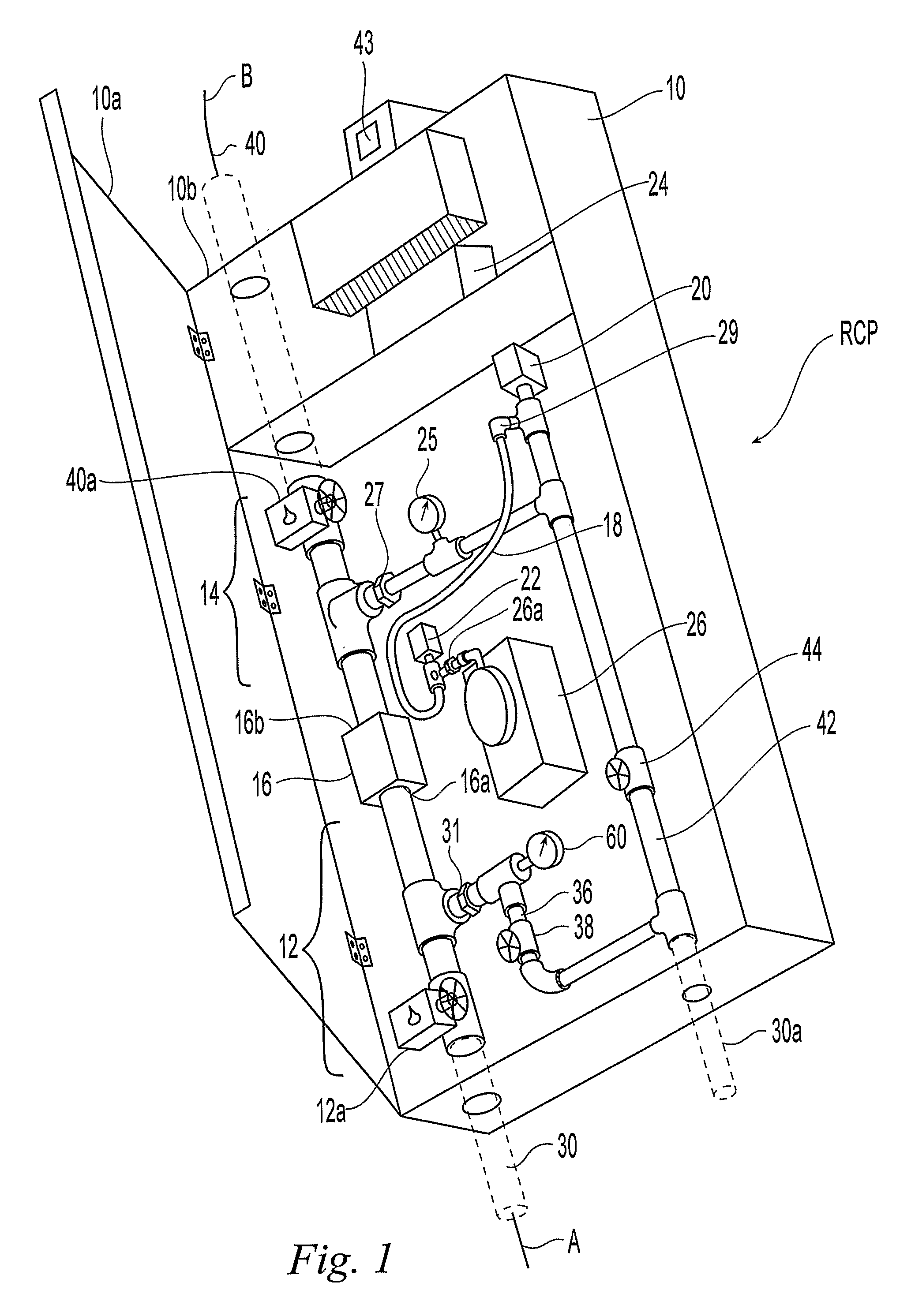
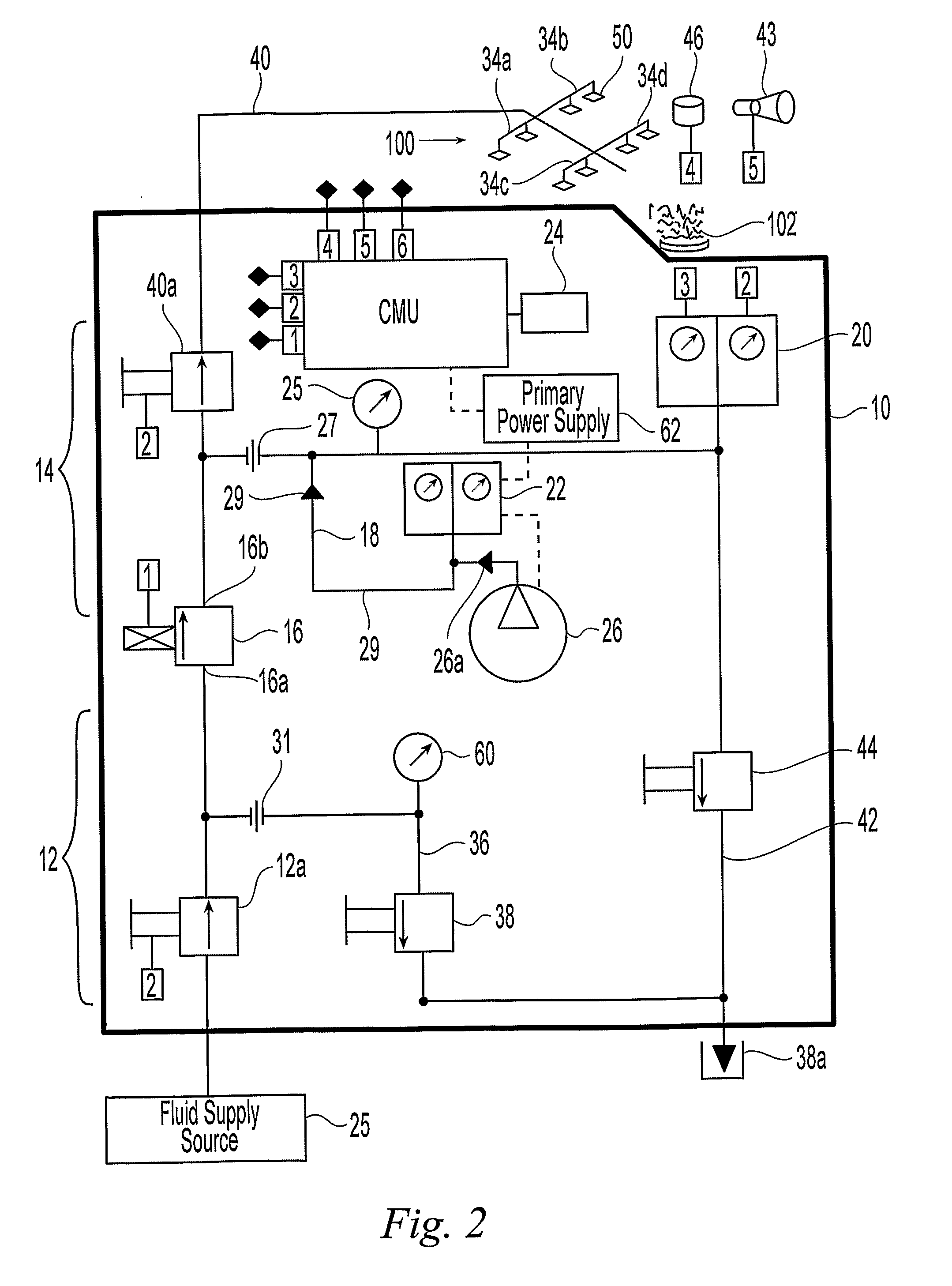
[0037]FIGS. 1 and 2 illustrate the preferred embodiments. In particular, FIG. 1 illustrates a releasing control panel (“RCP”) for a fire protection system 100 in a residential application. As used herein, the term “residential” indicates a dwelling unit as defined in the 2002 Edition of the NFPA Standard 13, and similarly in the 2002 Edition of NFPA 13D and 13R, which can include commercial dwelling units (e.g., rental apartments, lodging and rooming houses, board and care facilities, hospitals, motels or hotels), to indicate one or more rooms, arranged for the use of individuals living together, as in a single housekeeping unit, that normally has cooking, living, sanitary, and sleeping facilities. The dwelling unit normally includes a plurality of compartments as defined in NFPA Standard 13, where generally each compartment is a space that is enclosed by walls and ceiling. The standards relating to residential fire protection, as promulgated by the National Fire Protection Associat...


PUM


Abstract

Systems, methods and aspect thereof for a fire protection system including a releasing control panel. In one aspect a fire protection system for a residential unit as defined in the 2002 Edition of the National Fire Protection Association Standard 13, 13D and 13R having at least one dwelling is provided. The fire protection system preferably includes a liquid supply source along a main line and a network of pipes in communication with the dwelling. The system includes at least one sprinkler in the network to discharge a fluid within about fifteen seconds of sprinkler activation. In addition, the system includes at least one fire control panel disposed between the main line and the pipe network to control release of a fire fighting fluid under various control modes. The system further include at least one fire detector disposed in the at least one dwelling and in communication with the at least one fire control panel. In one aspect of the preferred system is sectional control to the first and at least a second dwelling.

Description


Claims


Application Information

Patent Timeline
Owner TYCO FIRE PRODS LP
Why Eureka
Try Eureka