Lined clamp for hoses and control lines

a technology for hoses and control lines, applied in the field of clamps, can solve the problems of difficult and expensive repairs in the subsea environmen

Active Publication Date: 2008-11-20
INT CLAMPS
View PDF20 Cites 23 Cited by
  • Summary
  • Abstract
  • Description
  • Claims
  • Application Information

AI Technical Summary

Benefits of technology

[0007]A novel liner element suitable for use in the clamp described above can be positioned in each clamp half Each liner element is formed from a rubbery body having an inner face facing the control line and an outer face to face the inner surface of a clamp half Each liner element has an upper end and a lower end. The inner face of each liner element defines at least one semi cylindrical trough extending from the upper end to the lower end of the element. The outer face defines a protruding block spaced apart from the first end and the second end which is closely received by the depression in the clamp half.
[0008]A novel mounting assembly useful in the combination described above comprises a mounting base and a pair of U-bolts connected to the mounti...

Problems solved by technology

They also have to be reliable in their function, because...

Method used


Image

  • Lined clamp for hoses and control lines
  • Lined clamp for hoses and control lines
  • Lined clamp for hoses and control lines

Examples


Embodiment Construction

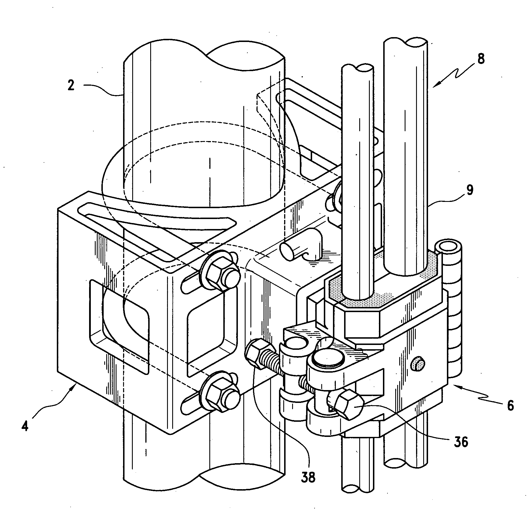
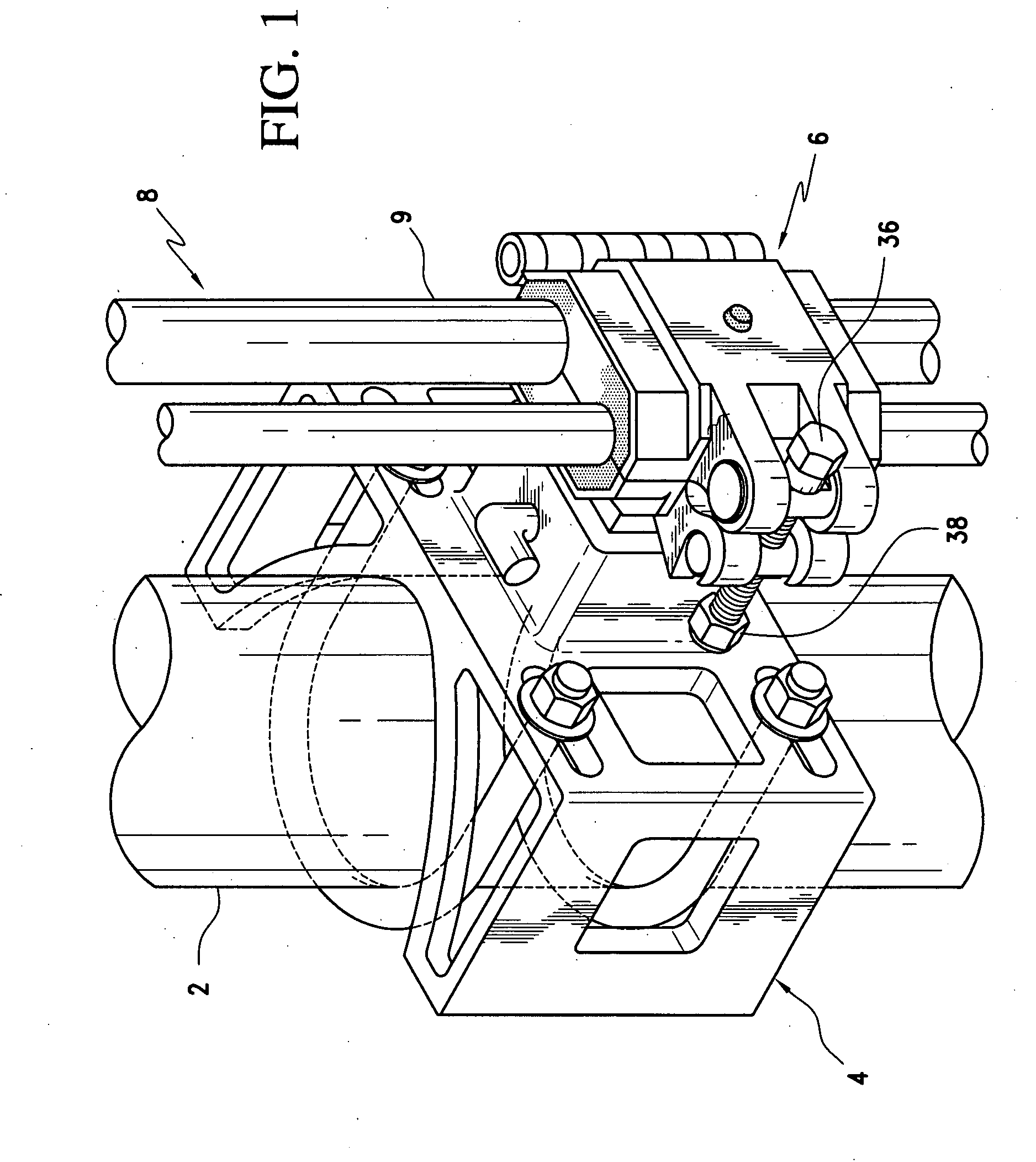
[0014]One embodiment of the invention is provided in the form of a combination of a tubular riser 2, a mounting assembly 4, a clamp assembly 6, and a control line assembly 8. The tubular riser is positioned in a body of water. The mounting assembly is positioned on the tubular riser. The clamp assembly is positioned on the mounting assembly. At least one control line 9 is positioned in the clamp assembly parallel to the riser.

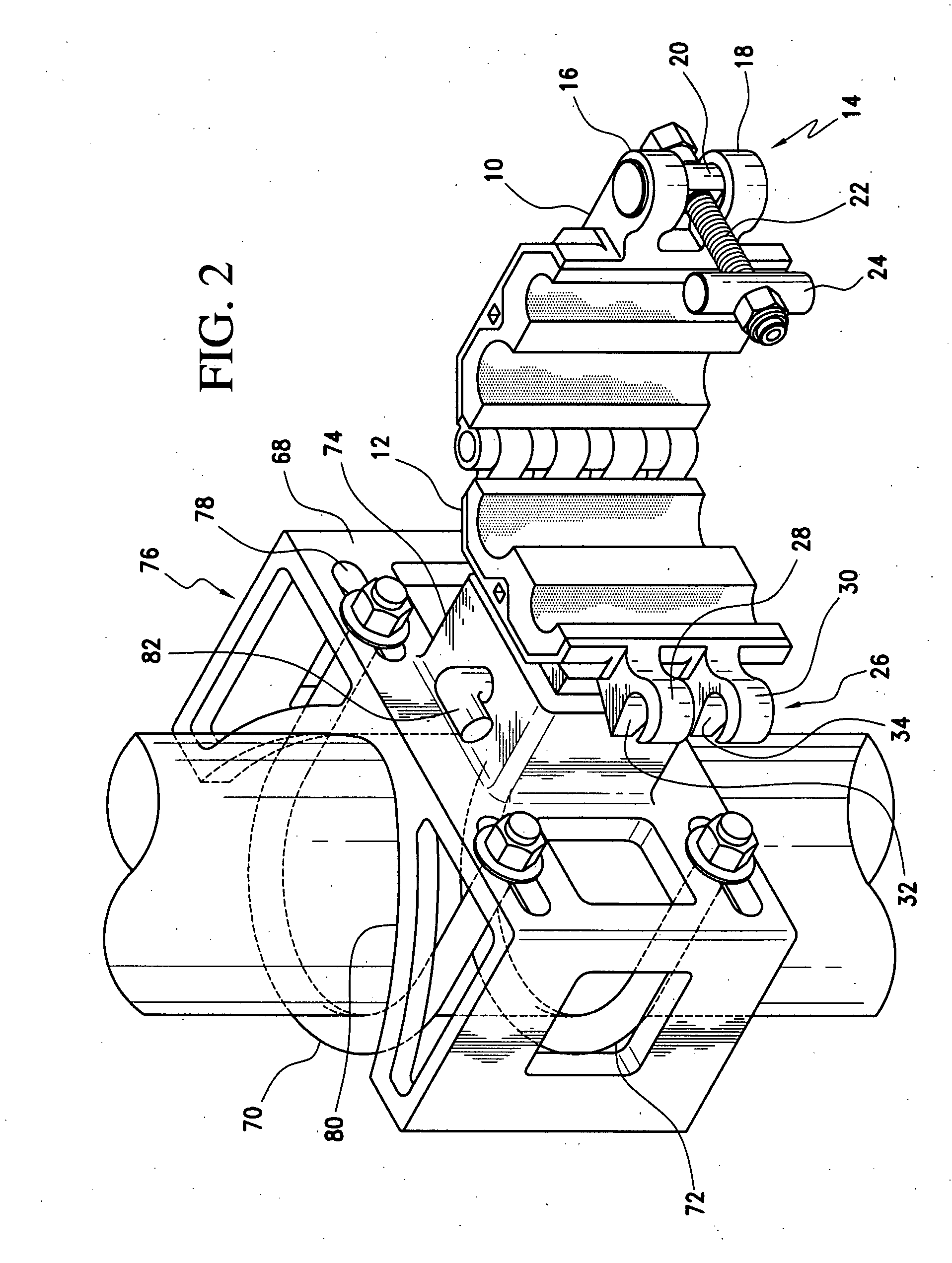
[0015]A novel clamp assembly useful in the combination comprises an upper clamp half 10 and a lower clamp half 12. Each clamp half is hingedly connected along a hinge edge of each clamp half to the other clamp half and latchably connected along a latch edge of each clamp half to the other clamp half by latch structure carried by each clamp half The latch structure 14 carried by the upper clamp half comprises a pair of parallel ears 16, 18 protruding transversely away from the latch edge of the upper clamp half and defining a pair of aligned boreholes, a pivot p...


PUM


Abstract

A clamp with liner and mounting base are provided for the attachment of control lines to a subsea riser. The clamp comprises an upper clamp half and a lower clamp half. Each clamp half is hingedly connected along a hinge edge of each clamp half to the other clamp half and latchably connected along a latch edge of each clamp half to the other clamp half by latch structure carried by each clamp half. The latch structure carried by the upper clamp half comprises a pair of parallel ears protruding transversely away from the latch edge of the upper clamp half and defining a pair of aligned boreholes, a pivot pin having a transverse borehole carried by the aligned boreholes through the ears, a bolt carried in the transverse borehole through the pivot pin, and a toggle bar having a threaded transverse borehole therethrough threadably mounted on the bolt. The latch structure carried by the lower clamp half comprises a pair of parallel ears protruding transversely from the latch edge of the lower clamp half and defining a pair of saddles facing away from the upper clamp half and contoured for close receipt of the toggle bar. Each clamp half has an inner surface defining a laterally bounded depression for receiving and locating a liner element having a portion shaped to fit the depression.

Description

FIELD OF THE INVENTION[0001]In one aspect, this invention relates to a clamp. In another aspect, this invention relates to a liner for a clamp. In further aspects, this invention relates to a mounting structure for a clamp. In additional aspects, this invention relates to a clamp and method for securing hoses and control lines to a subsea riser structureBACKGROUND OF THE INVENTION[0002]Subsea clamps for use in the offshore oil and gas industries have to be durable and rugged to withstand the rigors of use. They also have to be reliable in their function, because repairs in the subsea environment are difficult and expensive. It is also desirable that the clamps have few loose parts, because they are handled in an area where dropped parts can be lost overboard. It is further desirable that the clamps be padded, so as to reduce the risk of damaging the hoses and control lines secured by them.OBJECTS OF THE INVENTION[0003]It is an object of the invention to provide a clamp which is well...

Claims


Application Information

Patent Timeline
IPC IPC(8): F16L3/12
CPCE21B17/1035F16L3/237Y10T403/5766Y10T403/4916Y10T403/7011Y10T403/5761
Inventor MCCLURE, LAWRENCE M.GOODMAN, WILLIAM MAX
Owner INT CLAMPS
Why Eureka
Try Eureka