Coiled Transmission Line Pulse Generators

Inactive Publication Date: 2008-11-20
SCI ENG SOLUTIONS
View PDF6 Cites 23 Cited by
  • Summary
  • Abstract
  • Description
  • Claims
  • Application Information

AI Technical Summary

Benefits of technology

[0024]Charging and switching architectures will be provided to increase the pulse repetition rate capability and reliability of the system: including the possible use of spark gaps or solid state switches including electrically triggered devices such as Thyristors, MOSFETs or IGBT's; Photoconductive Solid-State Switches such as Silicon C

Problems solved by technology

However, a water pulse forming line would have to be over fifty feet long to produce a one microsecond pulse, making it unpractical for the long pulse parameter space.
Since no existing high voltage output switch can operate reliably at high repetition rates or for long life cycles, this topology is not practical for repetition rated devices.
Mar

Method used


Image

  • Coiled Transmission Line Pulse Generators
  • Coiled Transmission Line Pulse Generators
  • Coiled Transmission Line Pulse Generators

Examples


example 1

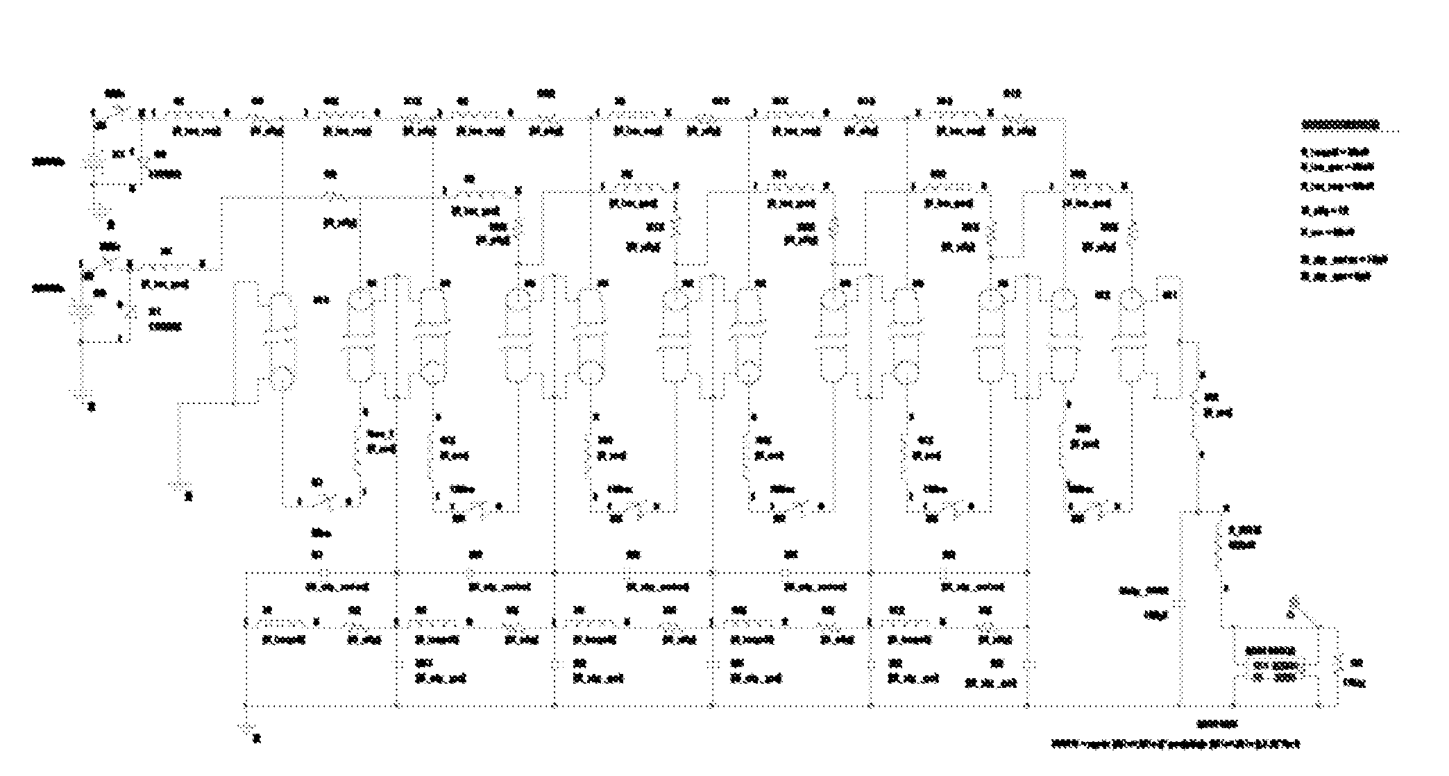
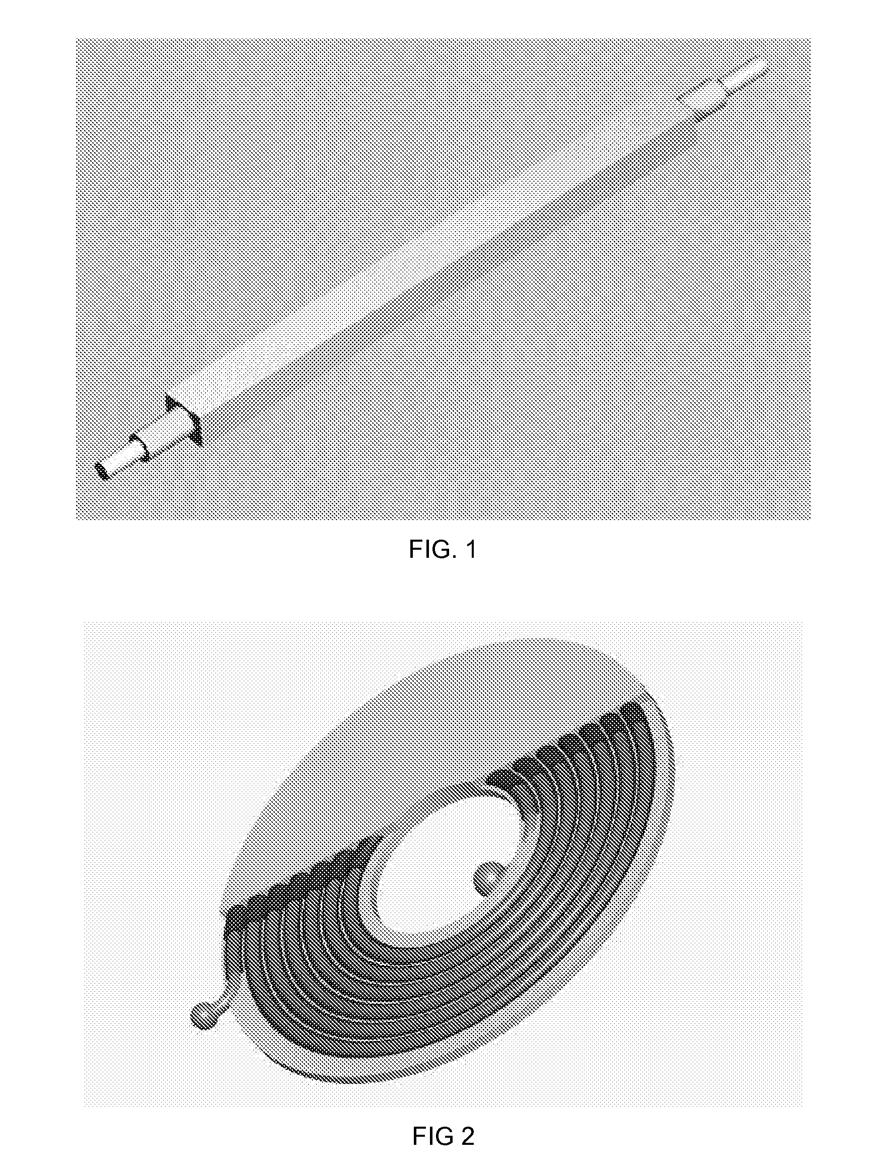
[0078]Many High Power Microwave devices, such as Magnetically Insulated Line Oscillators (MILO's), Relativistic Magnetrons, Ubitrons, traveling wave tubes, etc., require relatively flat-topped pulses. These devices range in impedance from approximately eight to one hundred Ohms and require pulse durations ranging from about 100 nanoseconds to more than 1 microsecond. The waveforms can be generated by connecting sets of Coiled Transmission Lines into a Marx generator configuration. Such a circuit; designed to drive a 500 kV, 200 ns flat-topped pulse into a forty Ohm relativistic magnetron; could consist of eleven Marxed CTL's charged to at least 91 kV. Numerous other extensions of the basic circuit concept are feasible. FIG. 17 demonstrates a single radially coiled 200 ns tri-plate coiled transmission line pulse generator equipped with a spark gap switch; whereas FIG. 18 illustrates the side view of a bi-polar, twelve stage, Tri-Plate Marxed coiled transmission line pulse generator c...

example 2

[0079]The accelerating cavities for linear accelerators are typically powered by radio frequency electromagnetic pulses that are produced by klystrons. This invention can satisfy the requirements of such klystrons: for example, a Photon Initiated Marxed-CTL pulse generator can produce low ripple 500 kV, 530A, 1.6 microsecond flattop pulses with rise and fall times of less than 100 nanoseconds at repetition rates of at least 120 Hz by Marxing thirty, 31 Ohm CTL's with solid state switches such as photon initiated thyristors.

example 3

[0080]Low impedance pulsers that produce high voltages and currents with flat-topped pulses can be very useful to calibrate voltage or current probes. A single linear or Coiled Transmission Line could produce a 50 kV pulse with currents as high as 50 kA for a one Ohm system. The voltage can be increased by configuring more than one solid dielectric Transmission Line into Marx or Blumlein circuit topologies. Several parallel, higher impedance devices could be used rather than a single low impedance device.

[0081]The preceding examples can be repeated with similar success by substituting the generically or specifically described elements and / or operating conditions of this invention for those used in the preceding examples. Numerous other applications and examples are available.

Experimental Results

Co-Axial Configuration:

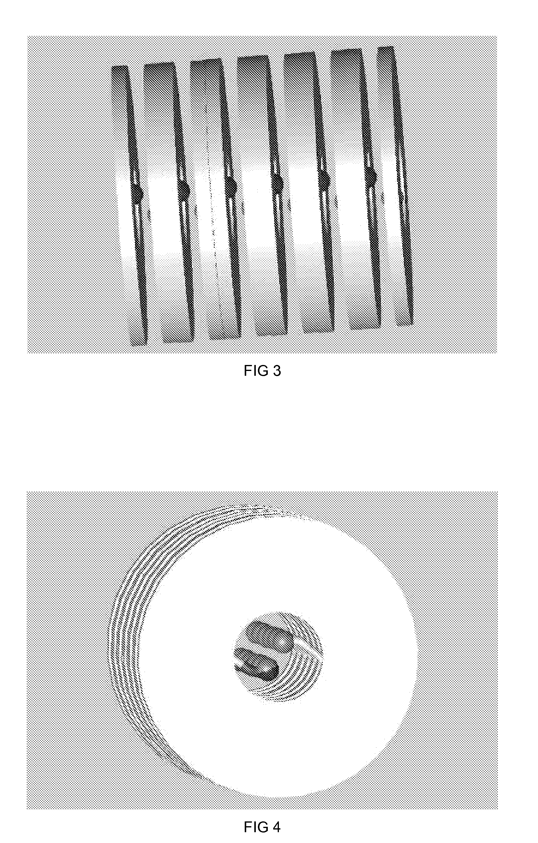
[0082]FIG. 20, FIG. 21, and FIG. 22 are photographs of the linear co-axial coiled transmission line prototype taken before and during the fabrication process. The slots...


PUM


Abstract

Methods and apparatus are provided for fabricating and constructing solid dielectric “Coiled Transmission Line” pulse generators in radial or axial coiled geometries. The pour and cure fabrication process enables a wide variety of geometries and form factors. The volume between the conductors is filled with liquid blends of polymers and dielectric powders; and then cured to form high field strength and high dielectric constant solid dielectric transmission lines that intrinsically produce ideal rectangular high voltage pulses. Voltage levels may be increased by Marx and/or Blumlein principles incorporating spark gap or, preferentially, solid state switches (such as optically triggered thyristors) which produce reliable, high repetition rate operation. Moreover, these pulse generators can be DC charged and do not require additional pulse forming circuitry, pulse forming lines, transformers, or an output switch. The apparatus accommodates a wide range of voltages, impedances, pulse durations, pulse repetition rates, and duty cycles. The resulting mobile or flight platform friendly cylindrical geometric configuration is much more compact, light-weight, and robust than conventional linear geometries, or pulse generators constructed from conventional components. Installing additional circuitry may accommodate optional pulse shape improvements. The Coiled Transmission Lines can also be connected in parallel to decrease the impedance, or in series to increase the pulse length.

Description

GOVERNMENT RIGHTS[0001]This invention was made with U.S. Government support under Contract No. DE-FG02-04ER84064 awarded by the Department of Energy. The Government has certain rights in this invention.DESCRIPTION[0002]1. Field of the Invention (Technical Field)[0003]The present invention relates to electro-mechanical components and electrical apparatus that are designed to generate nearly rectangular, high voltage pulses, which are often used to provide pulse power for physical apparatus such as high power microwave sources, lasers, particle beam generators, X-Ray generators, linear accelerators, etc. Although they may operate in a single shot mode, such pulse generators (frequently referred to as modulators) typically produce a pulse train that has specific voltage amplitude, current amplitude, pulse shape, pulse fidelity, pulse duration, pulse repetition rate, and duty cycle. For example, a pulse generator designed to drive a high power relativistic magnetron may produce a series...

Claims


Application Information

Patent Timeline
IPC IPC(8): H02N1/00
CPCB82Y30/00H02N11/004
Inventor MCDONALD, KENNETH FOX
Owner SCI ENG SOLUTIONS
Why Eureka
Try Eureka