Implantable Lead with a Stimulating Electrode and a Mapping Electrode that is Electrically Disconnectable

a technology of stimulating electrodes and electrodes, which is applied in the field of implantable leads, can solve the problems of unnecessary trauma to the endocardial and myocardial tissue, impact on the energy consumption of medical implants, etc., and achieve the effect of reducing the energy content required for evoking a response in the myocardial tissue, reducing the contact surface area, and increasing the impedance between the stimulating electrode surfaces and the myocardial tissu

Active Publication Date: 2008-11-20
ST JUDE MEDICAL
View PDF8 Cites 25 Cited by
  • Summary
  • Abstract
  • Description
  • Claims
  • Application Information

AI Technical Summary

Benefits of technology

[0012]An advantage of providing a separate, electrically disconnectable mapping electrode resides in the enabled reduction of the contact surface area between the stimulating surfaces of the distal lead end and the myocardial tissue following implantation of the medical device. Thus, following implantation and fixation of the distal end of the implantable lead at a suitable location in the heart, the mapping electrode is electrically disconnected from the heart stimulator, such that only the electrode intended for stimulation at said location is connected for delivering electrical stimuli to the myocardial tissue. Thereby, the impedance between the stimulating electrode surfaces and the myocardial tissue is increased, which results in the energy content required for evoking a response in the myocardial tissue being reduced. This, in turn, results in a reduction of the overall energy consumption of the heart stimulator.

Problems solved by technology

However, this procedure may be time-consuming and cause unnecessary trauma to the endocardial and myocardial tissue.
However, the presence of an electrode surface intended for use when finding a suitable fixation location has been observed to have an impact on the energy consumption of a medical implant.

Method used


Image

  • Implantable Lead with a Stimulating Electrode and a Mapping Electrode that is Electrically Disconnectable
  • Implantable Lead with a Stimulating Electrode and a Mapping Electrode that is Electrically Disconnectable
  • Implantable Lead with a Stimulating Electrode and a Mapping Electrode that is Electrically Disconnectable

Examples


Embodiment Construction

[0038]The following is a description of exemplifying embodiments in accordance with the present invention. This description is intended for describing the general principles of the invention and is not to be taken in a limiting sense. Like reference numerals indicate structures or elements having same or similar functions or constructional features.

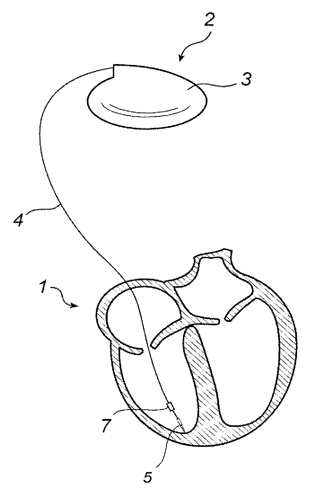
[0039]Referring first to FIG. 1, there is shown an implantable heart stimulator 2 in electrical communication with a human heart 1 via a cardiac lead 4 arranged for stimulation and sensing. Moreover, the heart stimulator 2 comprises electronic circuitry and a battery contained within a hermetically sealed pacemaker housing 3. The housing 3 comprises a metallic casing of titanium, enclosing the electronic circuitry and battery, and a molded plastic header portion, comprising connector blocks and apertures for receiving the connectors at the proximal ends of the cardiac leads.

[0040]The electronic circuitry comprises at least one pulse gener...


PUM


Abstract

An implantable lead for delivering electrical stimuli to a human heart has a stimulating electrode for transmitting electrical stimuli to the myocardium after implantation, and a mapping electrode for use during implantation. The mapping electrode is configured to deliver electrical stimuli to the heart and to sense intrinsic cardiac activity, for the purpose of finding a suitable fixation position in the myocardium. During the implantation procedure, the mapping electrode is electrically connected to the conductor. The lead is configured to electrically disconnect the mapping electrode from the conductor after a suitable fixation position has been determined.

Description

BACKGROUND OF THE INVENTION[0001]1. Field of the Invention[0002]The present invention generally relates to the field of implantable medical devices. More specifically, the present invention relates to an implantable lead for delivering electrical stimuli to a human heart, the lead having a proximal end for connection to an implantable medical device, and a distal end for fixation in the myocardium of a human heart.[0003]2. Description of the Prior Art[0004]Within the field of implantable heart stimulators, such as pacemakers, implantable leads are used for conveying electrical stimuli from the heart stimulator to the myocardium of a human heart. Before fixation of an implantable lead to a location in myocardial tissue of a human heart, the physician is interested in knowing whether the selected location is suitable for delivering electrical stimuli and possibly also for sensing electric intrinsic activity, i.e. electrical activity of the heart which is not induced by stimulation pul...

Claims


Application Information

Patent Timeline
Patent Type & Authority Applications(United States)
IPC IPC(8): A61N1/05
CPCA61N1/056A61N1/0573
Inventor ECKERDAL, JOHANDAHLBERG, KENNETH
Owner ST JUDE MEDICAL
Why Eureka
Try Eureka