

Primer, conductor foil with resin, laminated sheet and method of manufacturing laminated sheet
a technology of conductor foil and resin, which is applied in the direction of synthetic resin layered products, metal layered products, domestic applications, etc., can solve the problems of difficult to fully remove the conductor foil, short circuit, and easy to remain in the part intended to be removed, and achieve the effect of convenient manufacturing
- Summary
- Abstract
- Description
- Claims
- Application Information
AI Technical Summary
Benefits of technology
Problems solved by technology
Method used
Image

Examples
examples
[0157]Hereafter, some examples of the invention will be described in detail, but the invention is not limited to these examples.
Preparation of Resin Primer
examples 1-3
[0158]The starting materials shown in TABLE 1 were blended, and dissolved by stirring to obtain the resin primers of Examples 1-3. In TABLE 1, as bisphenol A epoxy resin, DER-331L (epoxy equivalent=184, Dow Chemical Co., Ltd., trade name) was used; as novolac phenol resin, HP-850N (hydroxyl group equivalent=106, Hitachi Chemical Industries Co., Ltd., trade name) was used; and as acrylic rubber, W-248DR (Shin-Nakamura Chemical Industries Co., Ltd., trade name) was used.
[0159]
TABLE 1Resin (g)Example 1Example 2Example 3Bisphenol A epoxy resin555Novolak phenol resin123Acrylic rubber0.61.21.7DBU (g)0.010.020.03MEK (g)9.912.214.6
example 4
[0160]100 g of phenoxy resin (YP-50, hydroxyl group equivalent=284, Toto Kasei Inc., trade name) and 330 g of cyclohexanone were introduced into a 1 L separable flask fitted with a reflux condenser, thermometer and stirrer, and the mixture heated with stirring to dissolve the resin. Subsequently, 41.9 g phenyl isocyanate and 0.3 g triethylamine were added, and reacted at 130° C. for 3 hours. Next, the product was reprecipitated in ethanol, and dried to give a phenoxy resin to which carbamate had been added. This resin was then dissolved in dimethylformamide (DMF) to give a concentration of 30 mass %, and the resin primer of Example 4 was thus obtained.
PUM
| Property | Measurement | Unit |
|---|---|---|
| roughness | aaaaa | aaaaa |
| roughness | aaaaa | aaaaa |
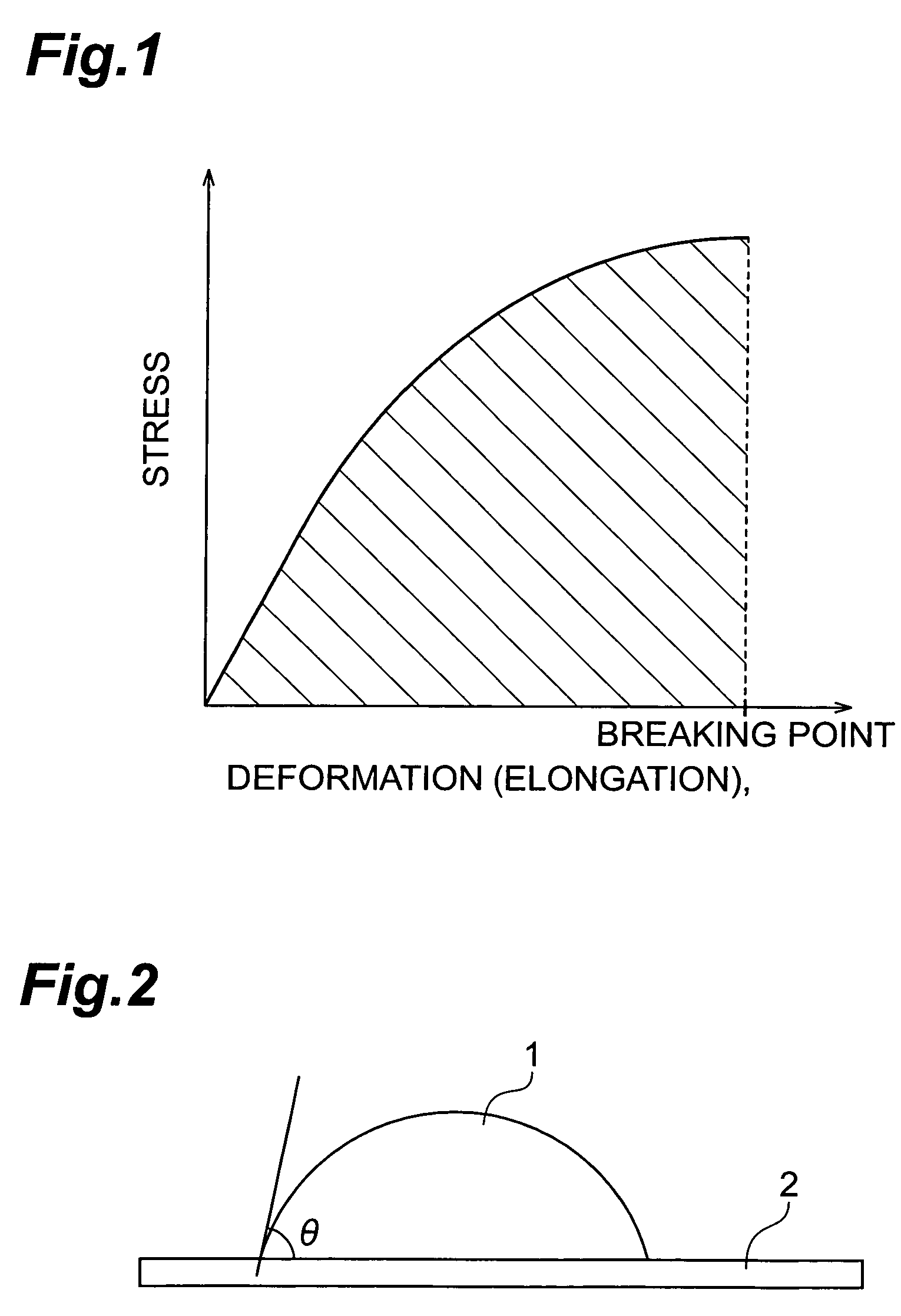
| contact angle | aaaaa | aaaaa |
Abstract
Description
Claims
Application Information