Vehicle Beverage Holder
a beverage container and beverage technology, applied in the field of beverage containers, can solve the problems of difficult shifting gears, difficult to hold a beverage container upright without spilling, and liquid may leak around the edge of the cup and lid, and achieve the effect of convenient adjustment and easy grasping
- Summary
- Abstract
- Description
- Claims
- Application Information
AI Technical Summary
Benefits of technology
Problems solved by technology
Method used
Image
Examples
second embodiment
[0065]FIG. 18 is two stacked container vessels 130 with lower necks that have diagonally aligned side walls 132. Formed inside the lower necks are integrally formed flexible arms 134.
[0066]It should be understood that the holder 10 may be manufactured and sold either as an ‘aftermarket product’ that is installed by the motor vehicle owner or it may be manufactured and installed by the motor vehicle manufacturer and incorporated into the center console as shown in FIG. 23.
[0067]FIG. 23 is a partial sectional, side elevational view of the beverage holder holding a large 64 fl. oz plastic container 200 with the two container vessels 132, 132′ stacked together.
[0068]Also shown in FIGS. 24—disclosed herein is another embodiment of the beverage holder 200 designed to be used with a vehicle's existing cup holder 300. In this embodiment, the beverage holder 200 includes a hollow base 220 with a cup holder insert 240 configured to fit into a cylindrical shaped cup holder 300. The insert 240 ...
first embodiment
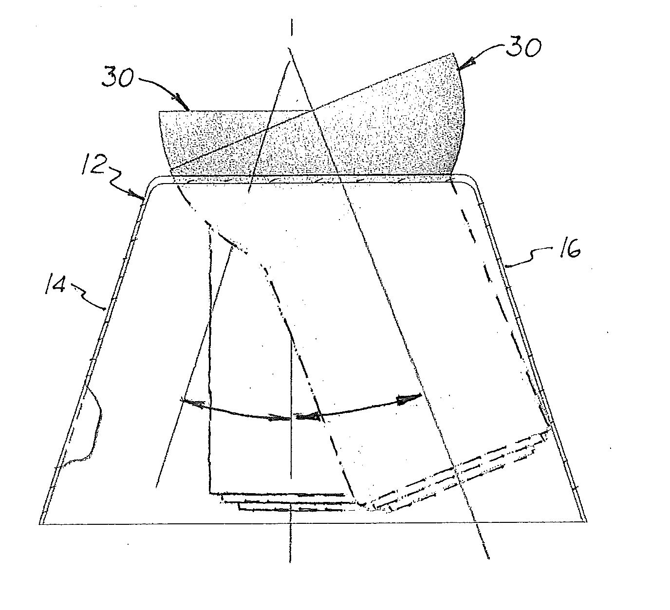
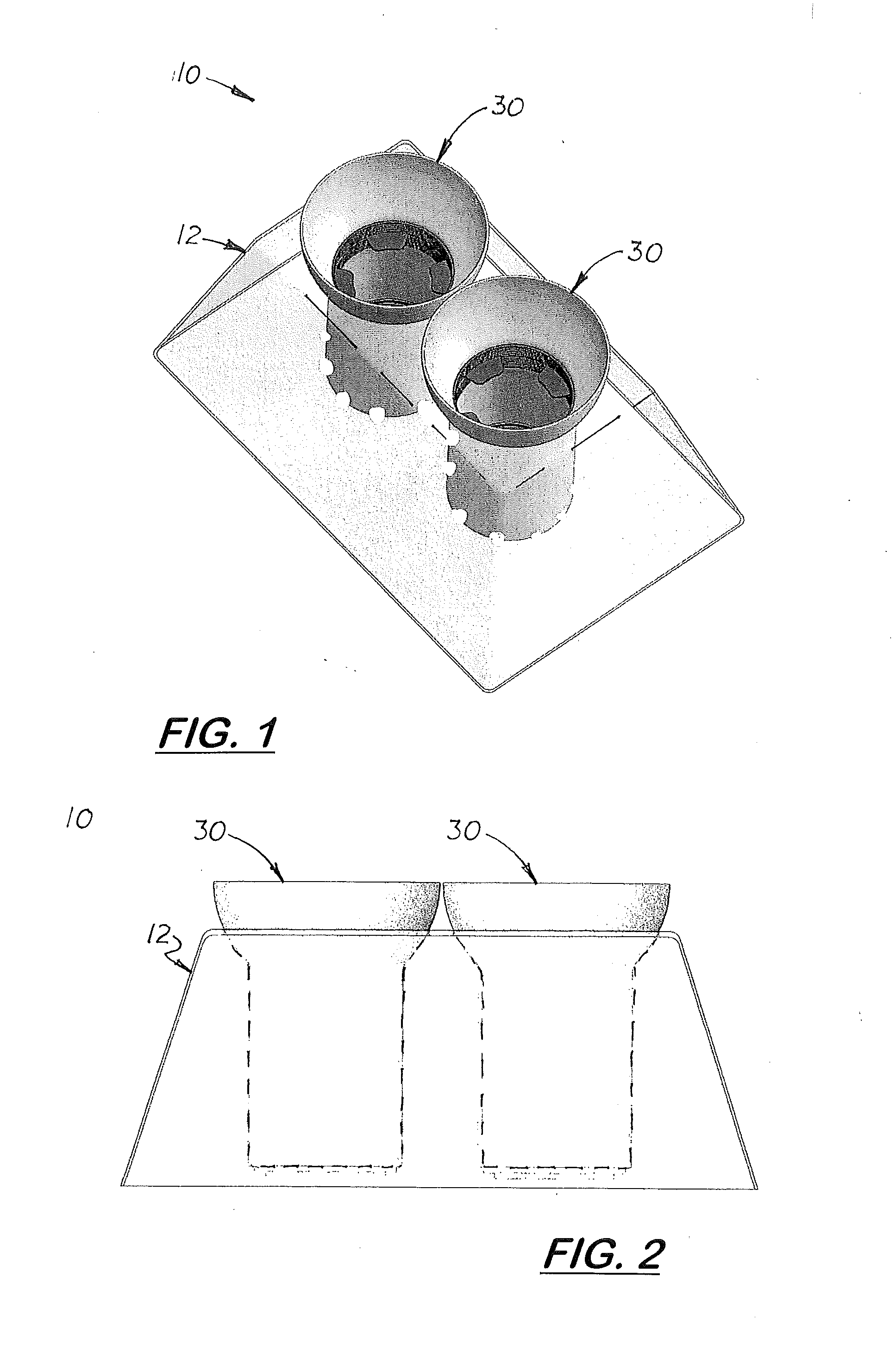
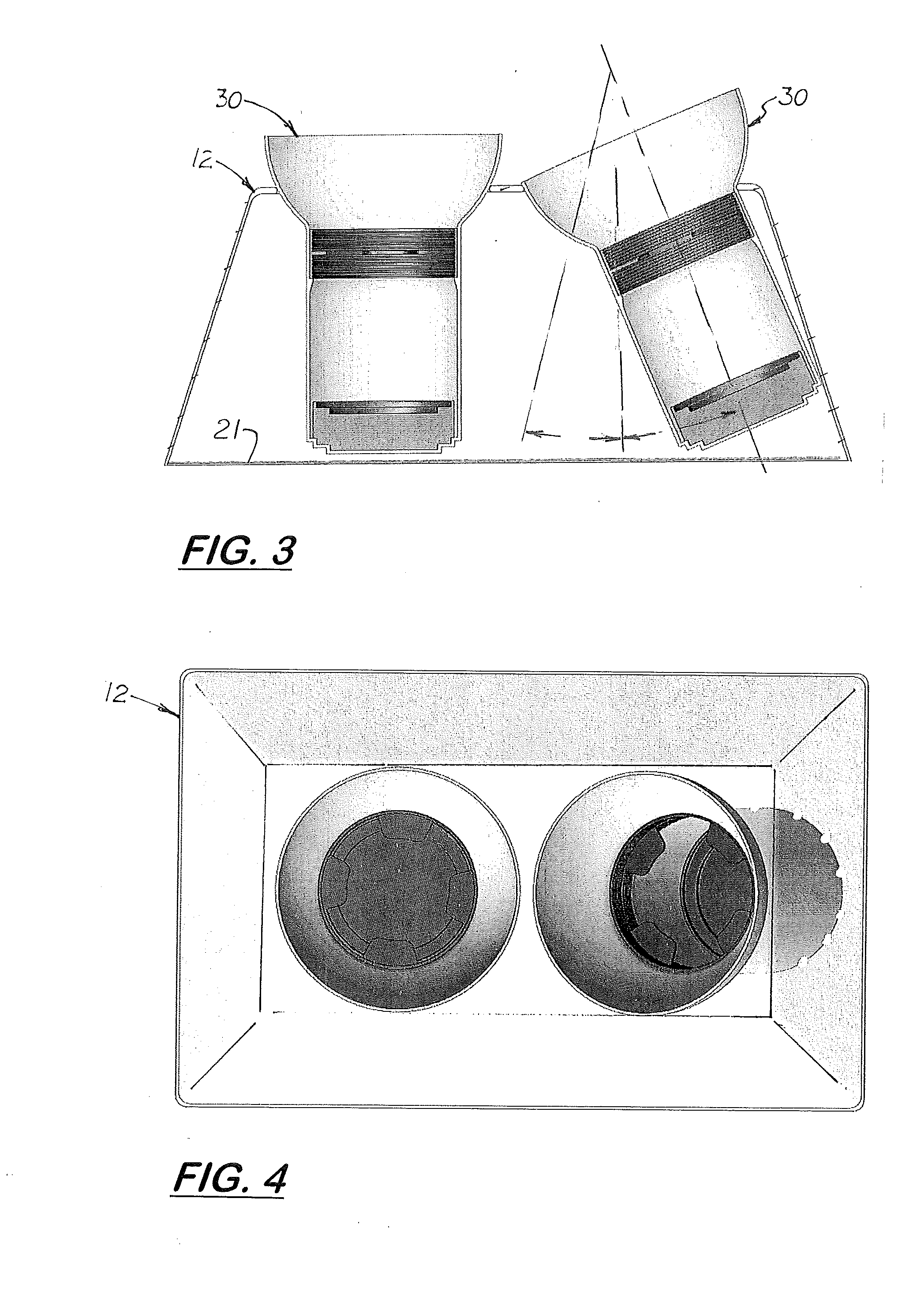
[0072]The container vessel 260 used with the base 220 configured to be inserted into a cup holder 300 is very similar to the container vessel 30 used in the first embodiment and includes half-spherical upper member 262 and a lower neck 265. The half-spherical upper member 262 may be configured to rest against the perimeter edge 226 formed around the base's hole 225 similar to the way the container vessel 30 rests against to edge 25 of base 12 shown in FIG. 6. In the embodiment, the hole 225 is slightly larger in diameter than the diameter of the upper member 262 and an inward extending support surface 234 may be formed base 220 has shown in FIGS. 25, 26, and 28. The support surface 234 supports and allows the upper member 260 to rotate, slide, and tilt from side to side. In the preferred embodiment, the support surface 234 is ring structure slightly smaller than the hole 225 and slightly smaller in diameter than the upper member 260 and slightly larger in diameter than the upper mem...
PUM
 Abstract
Description
Claims
Application Information
 - R&D
- Intellectual Property
- Life Sciences
- Materials
- Tech Scout
- Unparalleled Data Quality
- Higher Quality Content
- 60% Fewer Hallucinations
Browse by: Latest US Patents, China's latest patents, Technical Efficacy Thesaurus, Application Domain, Technology Topic, Popular Technical Reports.
© 2025 PatSnap. All rights reserved.Legal|Privacy policy|Modern Slavery Act Transparency Statement|Sitemap|About US| Contact US: help@patsnap.com


