Liquid Injector Assembly with a Flanged Connector Connection

Active Publication Date: 2009-09-24
FORD GLOBAL TECH LLC
View PDF11 Cites 5 Cited by
  • Summary
  • Abstract
  • Description
  • Claims
  • Application Information

AI Technical Summary

Benefits of technology

[0001]Selective Catalyst Reduction (SCR) catalysts and liquid reductant (e.g., hydrocarbon or urea solution) injected into engine exhaust ducts may be used for reducing engine-out NOx emissions. However, heat from the engine exhaust may cause reductant injectors to overheat and may cause solids to deposit on the injector tip. The solid deposits may in turn result in clogging of the injector orifice.
[0002]One approach used to address injector overheating may be to use a small V-band clamp for connecting the injector and its mounting structure to the exhaust passage. The V-band serves to potentially insulate the injector from engine exhaust heat, thereby reducing solid deposit buildup.
[0003]However, the inventors herein have recognized that connecting the injector to the mounting structure using a V-band clamp may require special tools and may be too cumbersome to allow fast and easy assembly in a mass production environment. Likewise, premature degradation of the V-band clamp, due to assembly installation variation, for example, may increase exhaust leakage.
[0005]In this way, it is possible to obtain a reliable, robust, and time-efficient connection of the injector with reduced contact surface area between potentially high temperature injector components and the injector via the seal positioned in the air gap formed by the stand-off.

Problems solved by technology

However, heat from the engine exhaust may cause reductant injectors to overheat and may cause solids to deposit on the injector tip.
The solid deposits may in turn result in clogging of the injector orifice.
However, the inventors herein have recognized that connecting the injector to the mounting structure using a V-band clamp may require special tools and may be too cumbersome to allow fast and easy assembly in a mass production environment.
Likewise, premature degradation of the V-band clamp, due to assembly installation variation, for example, may increase exhaust leakage.

Method used


Image

  • Liquid Injector Assembly with a Flanged Connector Connection
  • Liquid Injector Assembly with a Flanged Connector Connection
  • Liquid Injector Assembly with a Flanged Connector Connection

Examples


Embodiment Construction

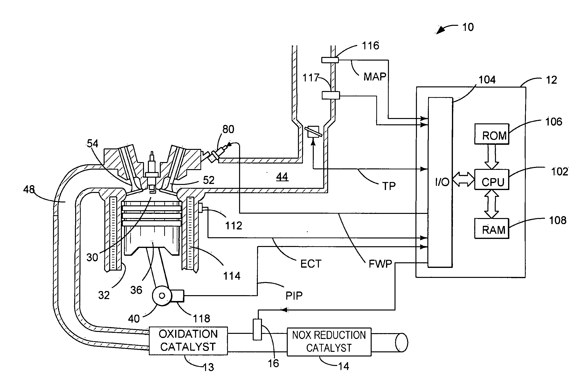
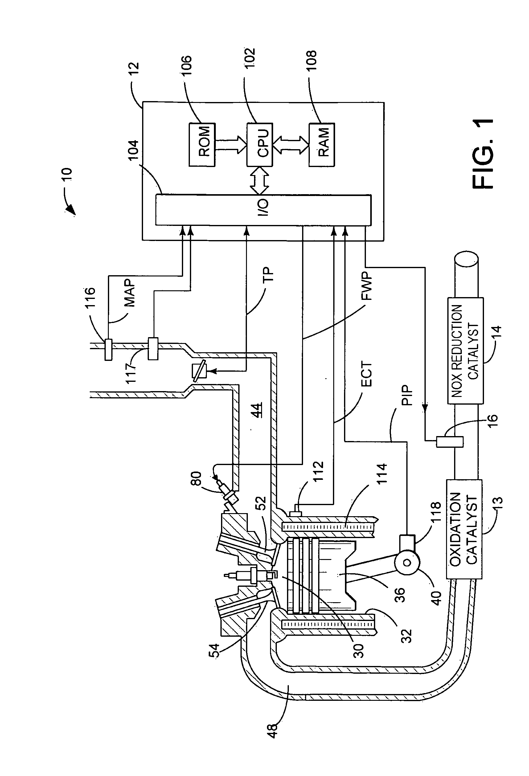
[0015]FIG. 1 is a schematic diagram of example environment in which an injector assembly for injecting liquid in a high temperature environment, such as injecting a liquid reductant into an engine exhaust for reducing NOx in a Selective Catalytic Reduction (SCR) catalyst, may be implemented. However, the various configurations described herein may be applied to other injection configurations, if desired, such as for injecting fuel into an intake duct, for example.

[0016]Internal combustion engine 10, comprising a plurality of cylinders, one cylinder of which is shown in FIG. 1, is controlled by electronic engine controller 12. Engine 10 includes combustion chamber 30 and cylinder walls 32 with piston 36 positioned therein and connected to crankshaft 40. Combustion chamber 30 is shown communicating with intake manifold 44 and exhaust manifold 48 via respective intake valve 52 and exhaust valve 54. Intake manifold 44 is also shown having fuel injector 80 coupled thereto for delivering ...


PUM


Abstract

A system for injecting from an injector into a duct of an engine system is provided. The system may include a first flange on a duct connection side, a second flange on an injector connection side, a stand-off separating the first flange from the second flange to form an air gap therebetween, and a seal offset from at least one of the first and the second flanges and located within the airgap and between the first flange and the second flange.

Description

BACKGROUND AND SUMMARY[0001]Selective Catalyst Reduction (SCR) catalysts and liquid reductant (e.g., hydrocarbon or urea solution) injected into engine exhaust ducts may be used for reducing engine-out NOx emissions. However, heat from the engine exhaust may cause reductant injectors to overheat and may cause solids to deposit on the injector tip. The solid deposits may in turn result in clogging of the injector orifice.[0002]One approach used to address injector overheating may be to use a small V-band clamp for connecting the injector and its mounting structure to the exhaust passage. The V-band serves to potentially insulate the injector from engine exhaust heat, thereby reducing solid deposit buildup.[0003]However, the inventors herein have recognized that connecting the injector to the mounting structure using a V-band clamp may require special tools and may be too cumbersome to allow fast and easy assembly in a mass production environment. Likewise, premature degradation of th...

Claims


Application Information

Patent Timeline
IPC IPC(8): F01N3/029B05B1/00F01N3/10
CPCF01N3/2066F01N3/36Y02T10/24F01N2610/03F01N2610/1453F01N2610/02Y02T10/12
Inventor POLLITT, DWAYNESHAIKH, FURQAN ZAFARCOOPER, SCOTT DONALDLEVIN, MICHAELBOGEMA, JOHN PAULZIMMERMAN, BRET ALANNICHOLS, GARY SCOTT
Owner FORD GLOBAL TECH LLC
Why Eureka
Try Eureka