Computer User Interface for a Digital Microform Imaging Apparatus

a computer and microform imaging technology, applied in computing, instruments, electric digital data processing, etc., can solve the problems of limited zoom range, inability to accommodate a range of reduction ratios, limited size and resolution of computer video displays, etc., to achieve meaningful and continuous display of capture boxes, and the effect of expanding the image for viewing

Inactive Publication Date: 2008-11-20
E IMAGE DATA
View PDF5 Cites 25 Cited by
  • Summary
  • Abstract
  • Description
  • Claims
  • Application Information

AI Technical Summary

Benefits of technology

[0012]Advantages of the present invention are that it provides a method and apparatus for enlarging the image for viewing without affecting the size of the image on the imaging sensor, without requiring a trial and error approach to view a specific piece of information of the micro image, and to provide a meaningful and continual display of the capture box.

Problems solved by technology

A typical microfilm reader may have a range of zoom or magnification available to accommodate a portion of the reduction ratio range; however, this zoom range is limited and does not accommodate all reduction ratios.
Further, in a microfilm reader of the type in the '654 patent, the optical system is enclosed and relatively fixed, and cannot be modified by a user to accommodate a range of reduction ratios for which it is not designed.
Computer video displays are limited in size and resolution.
When the micro image is sized to fit within the CUI display area it is difficult if not impossible to read because the image is both too small and the video display resolution is too low.
In this enlarged state, it is not possible to capture the micro image in its entirety to a single print or file.
When digitally zoomed in, you are not able to see the entire micro image and therefore unable to know which direction to pan (left, right, up, down) to view a specific piece of information of the micro image without using a trial and error approach.
Another drawback is that the capture box defining the area to be printed or captured is either no longer visible or, if it is visible, no longer defines the entire micro image area desired to be captured.
Known DMIAs / CUIs are not able to both optically zoom and digitally zoom, particularly concurrently.

Method used


Image

  • Computer User Interface for a Digital Microform Imaging Apparatus
  • Computer User Interface for a Digital Microform Imaging Apparatus
  • Computer User Interface for a Digital Microform Imaging Apparatus

Examples


Embodiment Construction

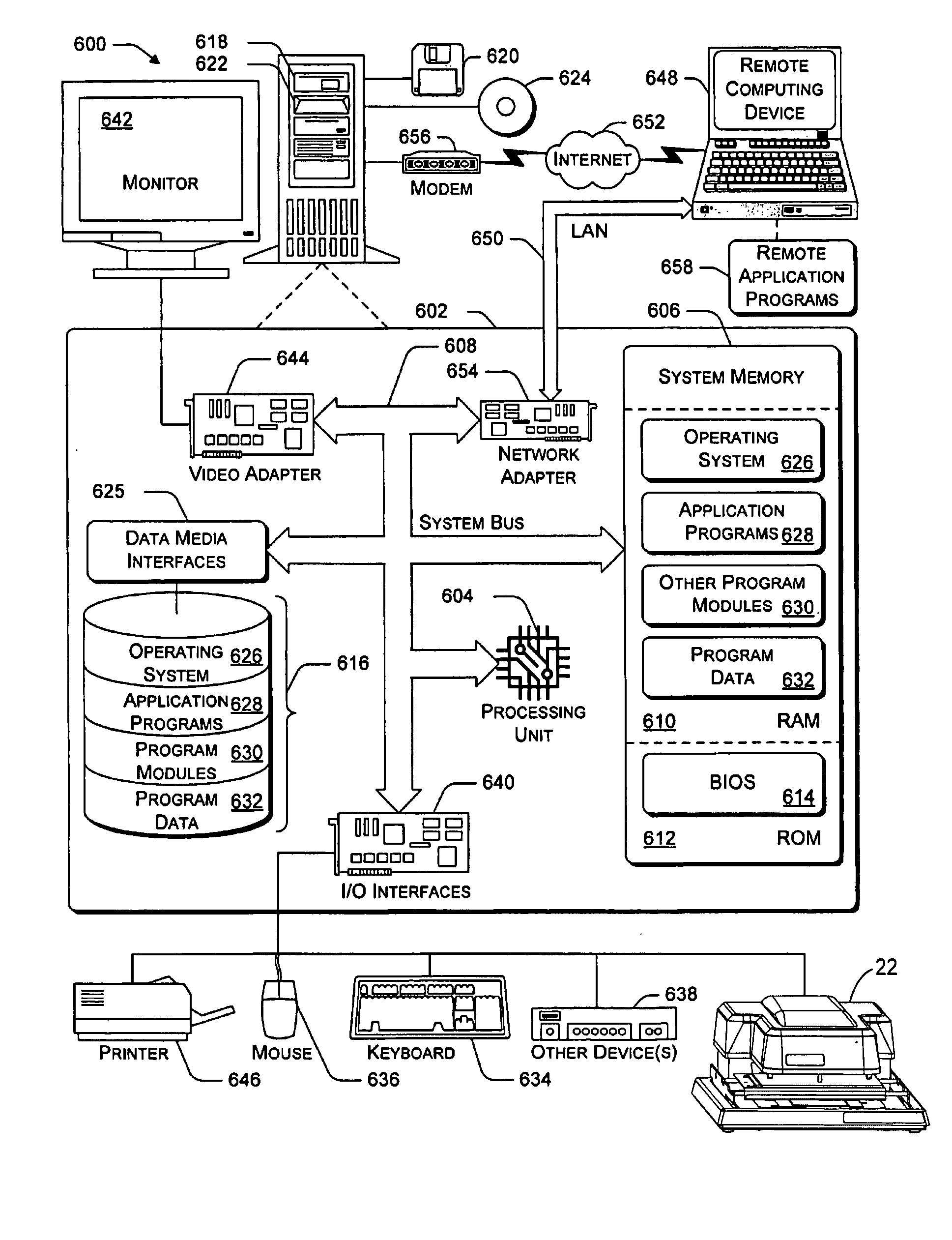
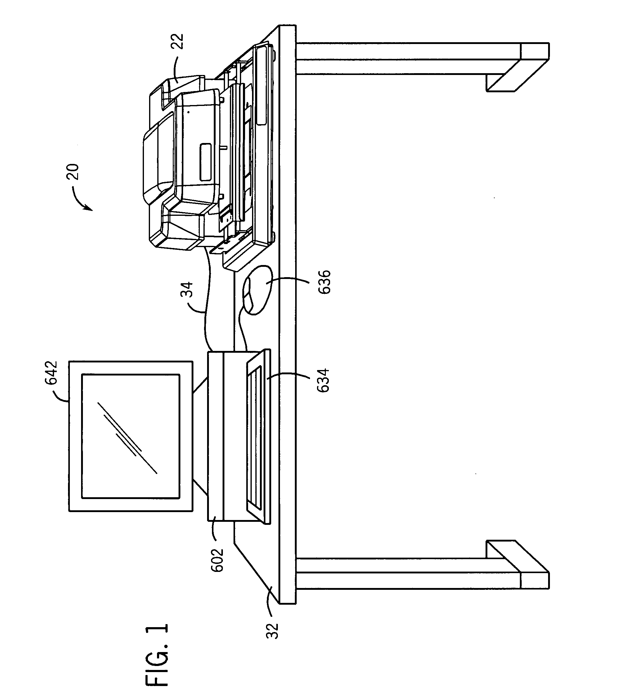
[0027]Referring now to the drawings, and more particularly to FIG. 1, there is shown a digital microform imaging system 20 which generally includes digital microform imaging apparatus (DMIA) 22 connected to a computer 602. Computer 602 can include one or more displays 642, and user input devices such as a keyboard 634 and mouse 636. DMIA 22 and computer 602 can be placed on a worksurface 32 of a desk, or other worksurfaces, for convenient access and ease of use. DMIA 22 can be electrically connected to computer 602 via cable 34, which may provide communication using a FireWire IEEE 1394 standard, for example. Although cable 34 is described as an electrical type cable, alternatively DMIA 22 and computer 602 can communicate via fiber optics, or wirelessly through infrared or radio frequencies, for example. Other details of computer 602 and the general computing environment are discussed in more detail below and shown in FIG. 9.

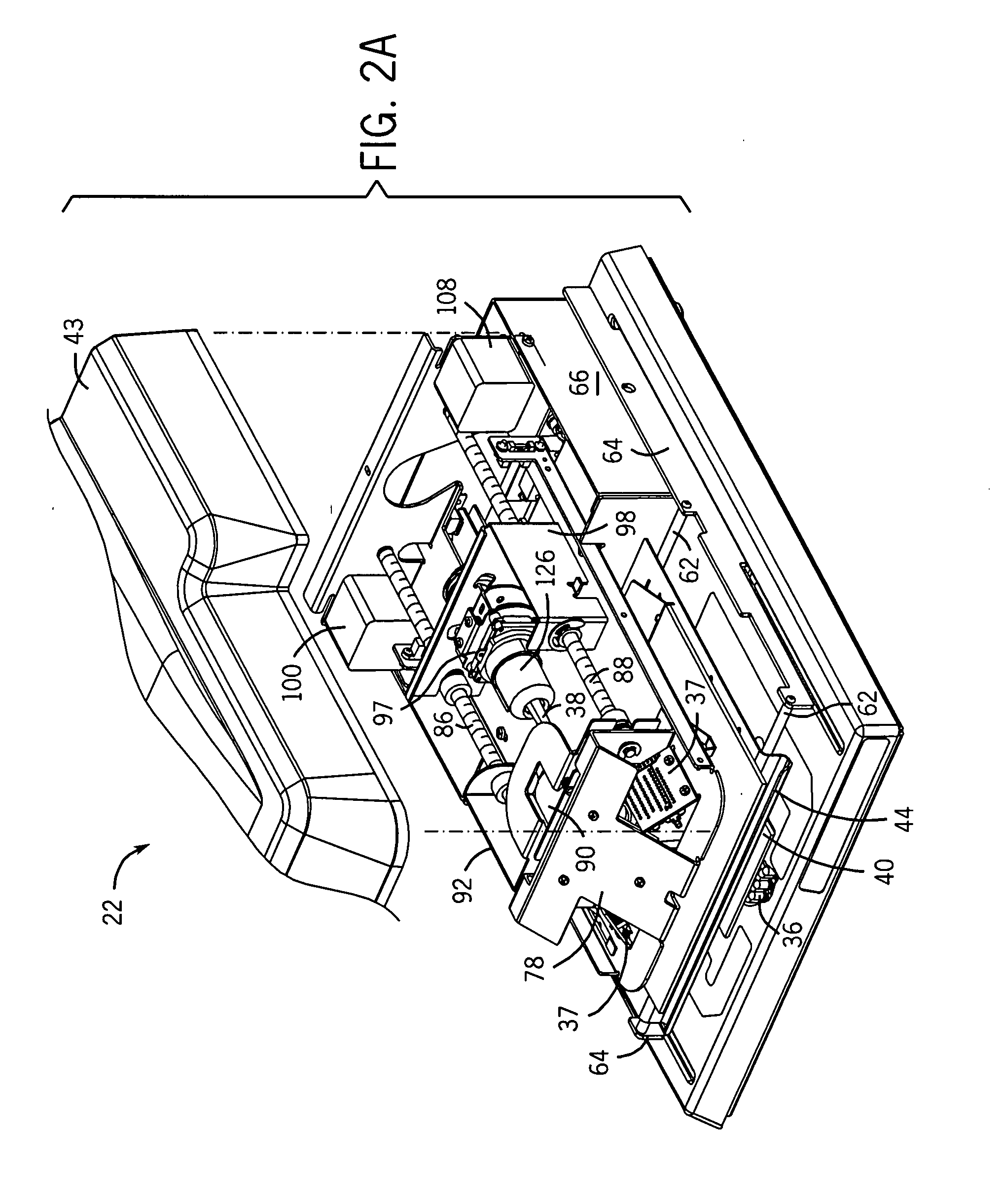
[0028]DMIA 22 is described in U.S. patent application Ser....


PUM


Abstract

A computer implemented method of viewing a microform segment which has been imaged by a digital microform imaging apparatus connected to a computer. The digital microform imaging apparatus images the microform segment and provides a corresponding image data of the microform segment to the computer. The method comprises the steps of: displaying the image data of the microform segment on a display connected to the computer using a computer user interface having a display area; and creating a magnification window within the computer user interface.

Description

FIELD OF THE INVENTION[0001]The present invention relates to a computer user interface for a digital microform imaging apparatus.BACKGROUND OF THE INVENTION[0002]Microform images are useful in archiving a variety of documents or records by photographically reducing and recording the document in a film format. Examples of typical microform image formats include microfilm / microfiche, aperture cards, jackets, 16 mm or 35 mm film roll film, cartridge film and other micro opaques. For example a microfiche article is a known form of graphic data presentation wherein a number of pages or images are photographically reproduced on a single “card” of microfiche film (such as a card of 3×5 inches to 4×6 inches, for example). Any suitable number of pages (up to a thousand or so) may be photographically formed in an orthogonal array on a single microfiche card of photographic film. The microfiche film may then be placed in an optical reader and moved over a rectilinear path until an image or a s...

Claims


Application Information

Patent Timeline
Patent Type & Authority Applications(United States)
IPC IPC(8): G06F3/048
CPCG03B21/10
Inventor KAHLE, TODD A.WESTOBY, JAMES H.
Owner E IMAGE DATA
Why Eureka
Try Eureka