Vertical surround parallax correction

a parallax correction and vertical surround technology, applied in the field of vertical surround parallax correction, can solve the problems of reducing the visual effect of the stereoscopic image, affecting the visual effect, and causing stress or discomfort, so as to reduce the parallax effect, enhance the visual effect, and enhance the effect of image viewing

Active Publication Date: 2007-10-11
REAID INC
View PDF7 Cites 135 Cited by
  • Summary
  • Abstract
  • Description
  • Claims
  • Application Information

AI Technical Summary

Benefits of technology

[0011] According to one aspect of the present design, there is provided a method for providing enhanced image viewing for a left frame and a right frame of a stereo pair. The left frame comprises left frame content and the right frame comprises right frame content. The method comprises, proximate one edge of the image pair, shifting left eye content laterally relative to right eye content. The lateral shifting tends to shift negative parallax elements toward positive parallax.
[0012] According to another aspect of the present design, there is provided a method of providing enhanced image viewing of a right eye view and a left eye view of a stereo pair. The method comprises identifying a plurality of substantially corresponding points in the left eye view and the right eye view and bringing the plurality of substantially corresponding points together by morphing the left eye view and the right eye view together proximate an edge of at least one of the left eye view and the right eye view based upon the plurality of substantially corresponding points. The bringing together reduces parallax effects of the stereo pair toward zero parallax at the edge.
[0013] According to a further aspect of the present design, there is provided a method of providing enhanced image viewing of a right eye view and a left eye view of a stereo pair. This method comprises cross fading portions of the left eye view and right eye view approaching the left and right image edges to reduce or eliminate parallax effects near image edges.

Problems solved by technology

Beyond certain values the image becomes uncomfortable to view (FIG. 1D), or because of system constraints undesirable artifacts appear which contribute to difficulty in viewing the stereoscopic image.
This can produce stress or discomfort or what people sometimes call “eyestrain.”
This imaging artifact never occurs in the visual world so people have no ready way to articulate what is being seen.

Method used


Image

  • Vertical surround parallax correction
  • Vertical surround parallax correction
  • Vertical surround parallax correction

Examples


first embodiment

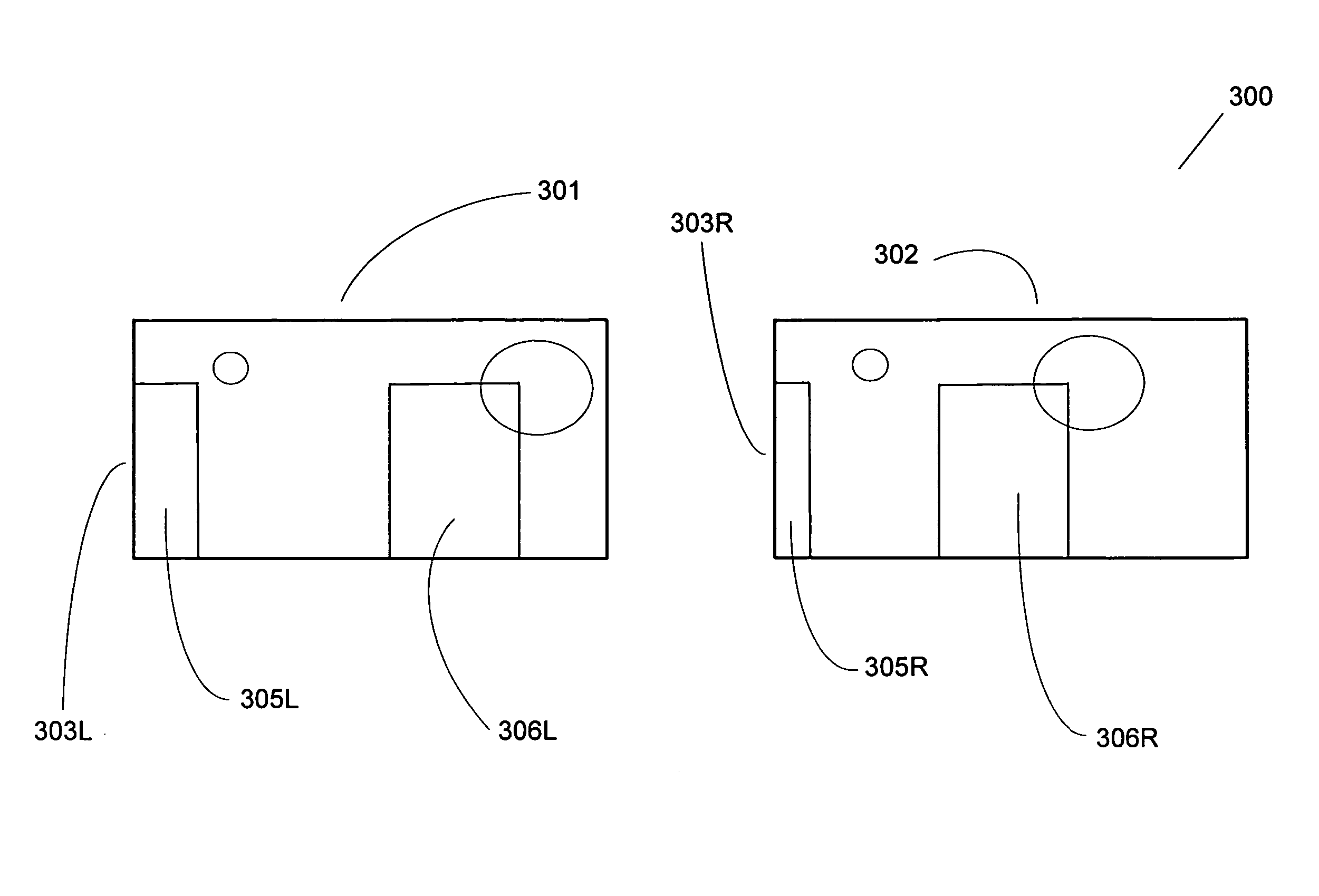
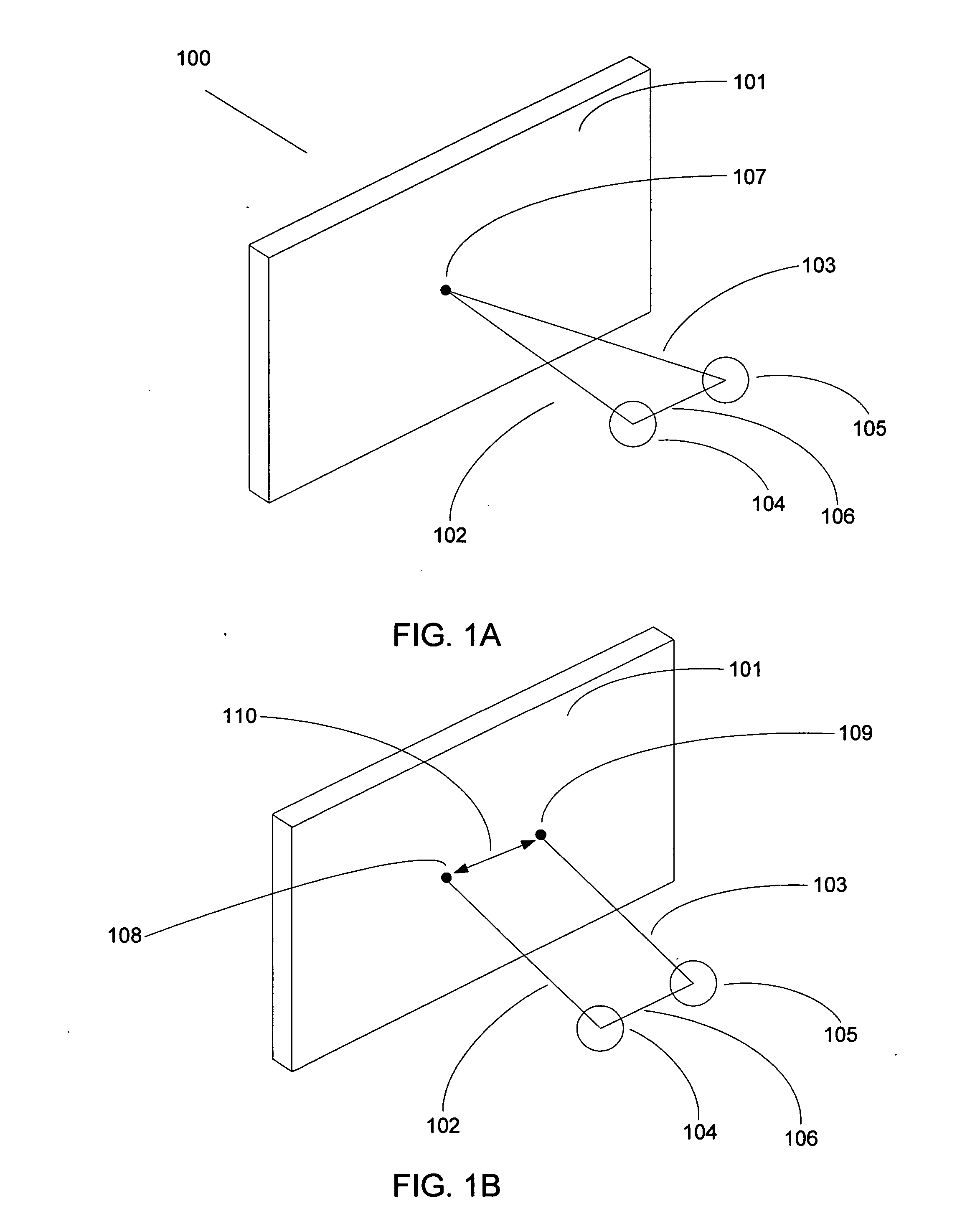
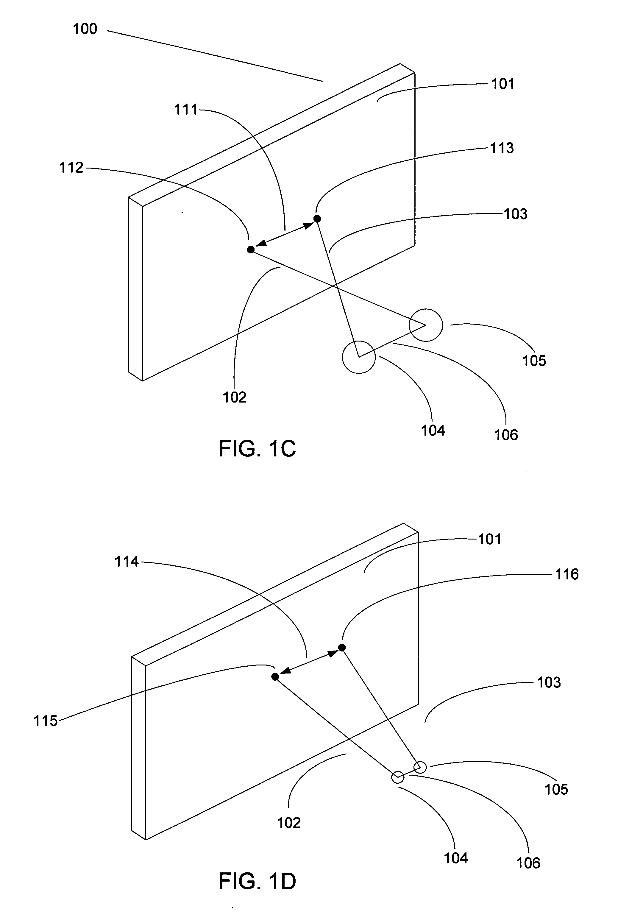
[0045] The first embodiment, illustrated using FIGS. 3A, 3B, 4A, 4B, and 4C, stretches either or both of the left and right edges of either or both of the images of the stereo pair (for example, stretching one edge of one stereo pair element, and stretching the opposite edge of the other stereo pair element), causing the parallax values to gradually decrease over the screen area adjacent to the surrounds' vertical edges at a measured rate so as to be unobtrusive. This edge stretching tends to reduce the troublesome negative parallax values to at or near a zero value. In other words, the system can adjust or stretch one of the images of the stereo pair so that its image points are more in correspondence with the other perspective view's image points. The result is that negative parallax is reduced to zero or near zero by setting the convergence of the image in such a way that the zero parallax location departs from a plane in camera space and is made to vary as a function of screen l...

second embodiment

[0059] The second embodiment uses image morphing of one or both of the images of the stereo pair to cause the parallax values to gradually decrease over distance at a measured rate to be both unobtrusive and reduce the troublesome negative parallax values to zero or nearly zero adjacent to the screen surround. This embodiment in effect reduces the entire parallax extent of the region adjacent to the surround to zero since the morphing approach causes all image points to correspond thereby flattening the image. This flattening of the image, or controlled reduction to planar, at the vertical surround region, serves to eliminate the conflict of cues.

[0060] In order to reduce overall parallax, specific scene elements are represented in both the left-eye and right-eye views with corresponding left and right points brought into correspondence by means of an image morphing process. All such homologous points are made to correspond by mapping and matching respective horizontal positions. As...


PUM


Abstract

Three general designs for reducing parallax in a moving picture are disclosed. One design comprises stretching graphics content near the left and right frame edges of stereo pair elements in order to modify parallax settings. A second design comprises identifying a plurality of substantially corresponding points in a left eye view and right eye view and bringing the plurality of substantially corresponding points closer together using a morph technique. The third design entails fading a portion of a right eye view with a portion of a left eye view near or proximate an edge of the image.

Description

BACKGROUND OF THE INVENTION [0001] 1. Field of the Invention [0002] This present invention relates to displaying both plano-stereoscopic images and autostereoscopic images. More specifically, the present design relates to eliminating the conflict of cues that occurs at the vertical edges of the screen surround when objects having negative parallax values are partially occluded by the surround. [0003] 2. Description of the Related Art [0004] Plano-stereoscopic images are images made up of a left and a right perspective image and are most often viewed using an individual selection device, or eyewear. Autostereoscopic images are defined as stereoscopic images that can be viewed without the use of an individual selection device as image selection takes place at the screen or display surface. While plano-stereoscopic imaging is predominantly discussed herein, a worker skilled in the art will be able to understand the changes that can be implemented to apply these teachings to autostereos...

Claims


Application Information

Patent Timeline
Patent Type & Authority Applications(United States)
IPC IPC(8): H04N13/00G06T19/00
CPCH04N13/0003H04N2213/002H04N13/0033H04N13/144H04N13/10H04N13/00
Inventor LIPTON, LENNYAKKA, BOB
Owner REAID INC
Why Eureka
Try Eureka