Fire extinguishing device

a technology of fire extinguishing device and fire extinguishing device, which is applied in fire rescue and other directions to achieve the effect of convenient use, compactness and low cos

Inactive Publication Date: 2008-11-27
SIAM SAFETY PREMIER
View PDF29 Cites 31 Cited by
  • Summary
  • Abstract
  • Description
  • Claims
  • Application Information

AI Technical Summary

Benefits of technology

[0009]The object of this invention is to provide an inexpensive, compact and easily used device,...

Problems solved by technology

These preconditions to a reusable device, especially with respect to a device upon which lives and property would depend, it is felt economically prejudic...

Method used


Image

  • Fire extinguishing device
  • Fire extinguishing device
  • Fire extinguishing device

Examples


Embodiment Construction

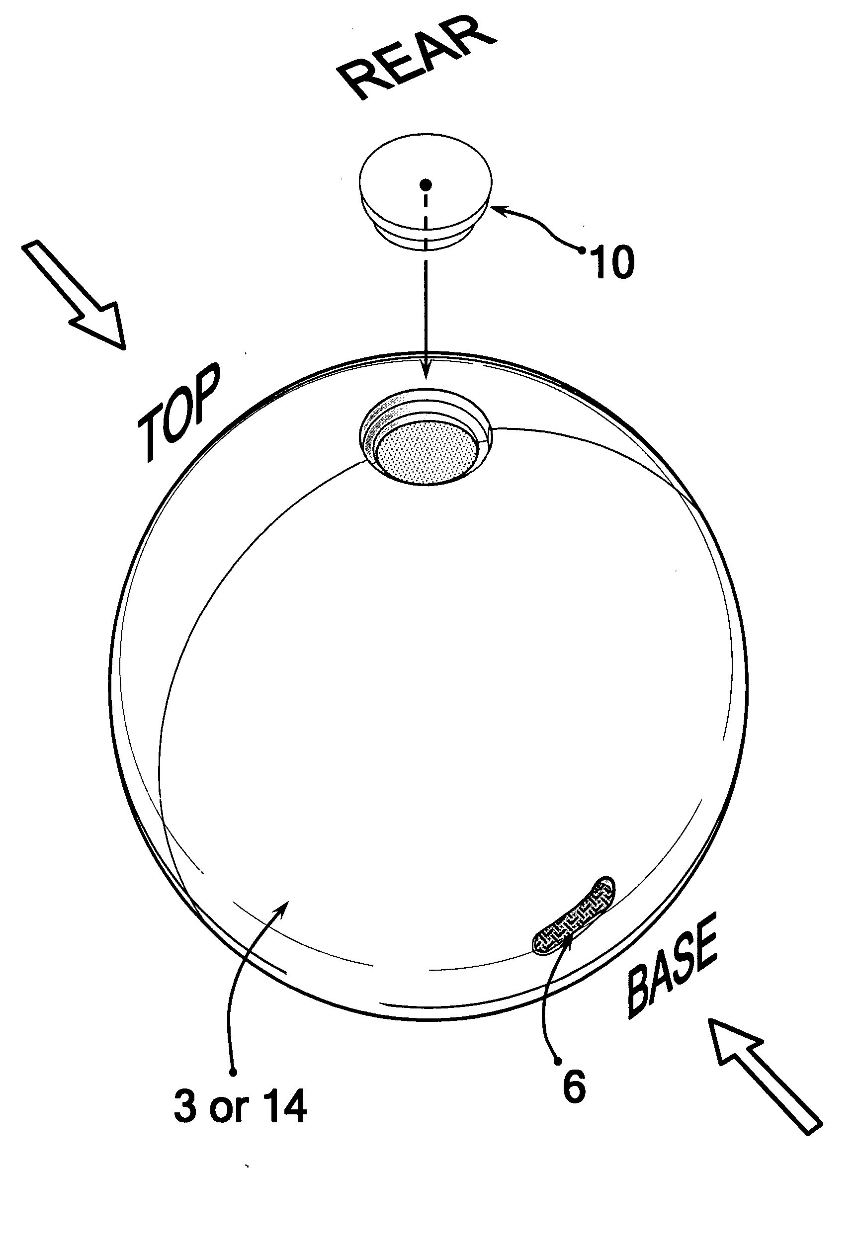
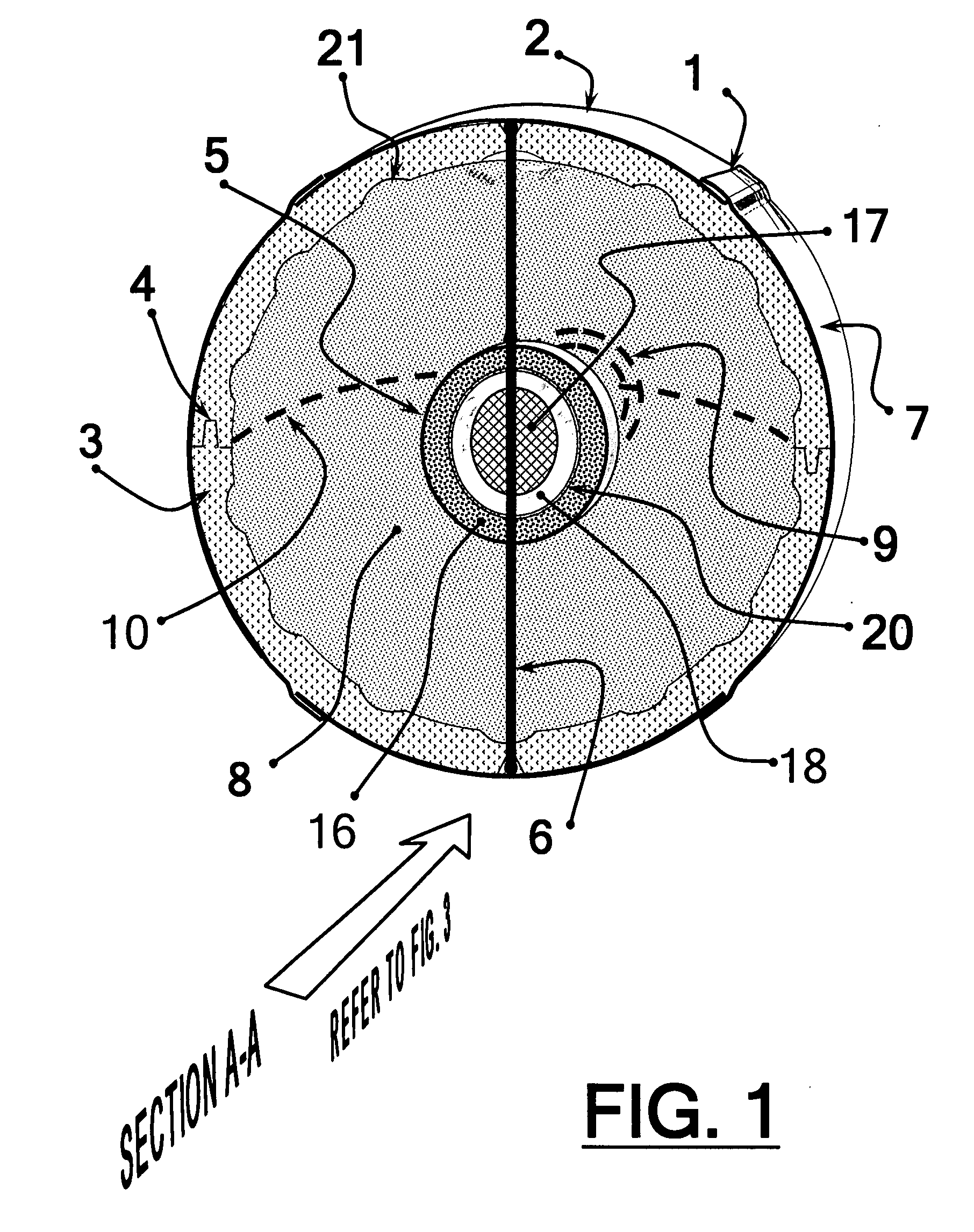
[0060]To meet the prescribed specification in the Summary, the containment vessel, seen in FIG. 1 and other drawings as 3, of the present invention utilizes lightweight, low density, rigid plastic foam as the preferred material, and specify among the current best choices, EPS (expanded polystyrene foam). Environmentally friendly, this material is molded into the required component shape, of which the preferred embodiment would require a hemisphere, because the sphere assembled from it is basic and efficient in terms of manufacture, the ratio of interior volume relative to surface area is highest, and thus the size of the device is minimized, as well as being that shape which results in the most evenly omni-directional dispersal pattern when utilized.

[0061]In a spherical exterior embodiment, half of the rim of each hemisphere could feature a tongue protrusion and matching groove 4 on the other half of the rim—or other joint features, excepting a small portion of the rim reserved for ...


PUM


Abstract

An explosive fire extinguishing device is used in interior or localized exterior environments. The force of detonation is minimalized through the use of low-density, low-mass components. A container is composed of a lightweight casing of rigid plastic foam or other suitably frangible material, with an abrasion-resistant, thin plastic, protective, exterior sheathing. Within an internal cavity of the device, the above-mentioned low-yield pyrotechnic detonator is located at or near the center of mass, and is actuated by fuse cords secured at or near the exterior surface. An interior volume of a hollow casing is charged with fire-retardant chemical agents, including dry powders, two-part reactants, liquid components or others, singly or in combination.

Description

CROSS-REFERENCE TO RELATED APPLICATIONS[0001]U.S. Patent Documents798623September 1905Poole et al.870479November 1907Stanley1458972June 1923Braude1482522February 1924Morriss1565036December 1925Tank2306321December 1942Roberts2759547August 1956Zabriskie2873806February 1959Bittner3446287May 1969Hook3833063September 1974Williams3980139September 1976Kirk4964469October 1990Smith5232053August 1993Gillis5588493December 1996Spector et al.5894891April 1999Rosenstock et al.5894892April 1999Huang6012531January 2000Ryan6050343April 2000Garcia Calvo6056063May 2000Hung6796382September 2004Kaimart7028782April 2006Richardson7121354October 2006Munson, Jr.7147061December 2006Tsutaoka, et al.7083000August 2006Edwards, et al.7090029August 2006Cleary, et al.STATEMENT REGARDING FEDERALLY SPONSORED RESEARCH OR DEVELOPMENT[0002][Not Applicable]REFERENCE TO A SEQUENCE LISTING, A TABLE, OR A PROGRAM LISTING COMPACT DISC APPENDIX[0003][Not Applicable]BACKGROUND OF THE INVENTION[0004]The invention relates to fi...

Claims


Application Information

Patent Timeline
IPC IPC(8): A62C8/00
CPCA62C3/025A62C19/00A62C35/08A62C37/48
Inventor KAIMART PHANAWATNAN(WORADECH)
Owner SIAM SAFETY PREMIER
Why Eureka
Try Eureka