Perforating gun and detonator assembly

a technology of perforating guns and detonators, applied in the direction of blasting cartridges, fluid removal, weapons components, etc., can solve the problems of inability to falsely connect, easy twisted and crimped, and inability to accurately conn

Active Publication Date: 2016-03-03
DYNAENERGETICS
View PDF5 Cites 52 Cited by
  • Summary
  • Abstract
  • Description
  • Claims
  • Application Information

AI Technical Summary

Problems solved by technology

Since the electrical wire must extend through much of the perforating gun assembly, it is easily twisted and crimped during assembly.
In addition, when a wired detonator is used it must be manually connected to the electrical wire, which has lead to multiple problems.
Due to the rotating assembly of parts, the wires can become torn, twisted and/or crimped/nicked, the ...

Method used


Image

  • Perforating gun and detonator assembly
  • Perforating gun and detonator assembly
  • Perforating gun and detonator assembly

Examples


Embodiment Construction

[0018]Reference will now be made in detail to embodiments. Each example is provided by way of explanation, and is not meant as a limitation and does not constitute a definition of all possible embodiments.

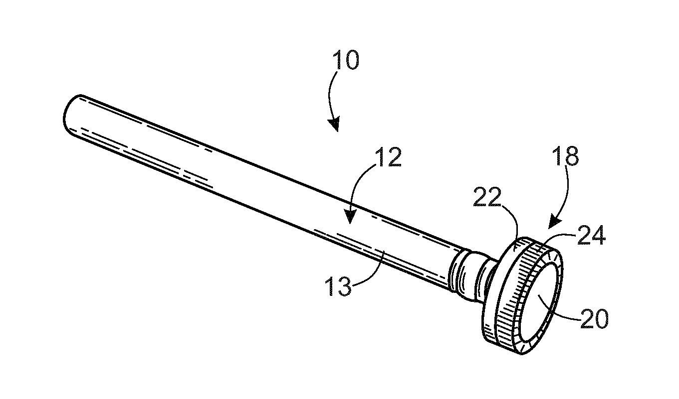
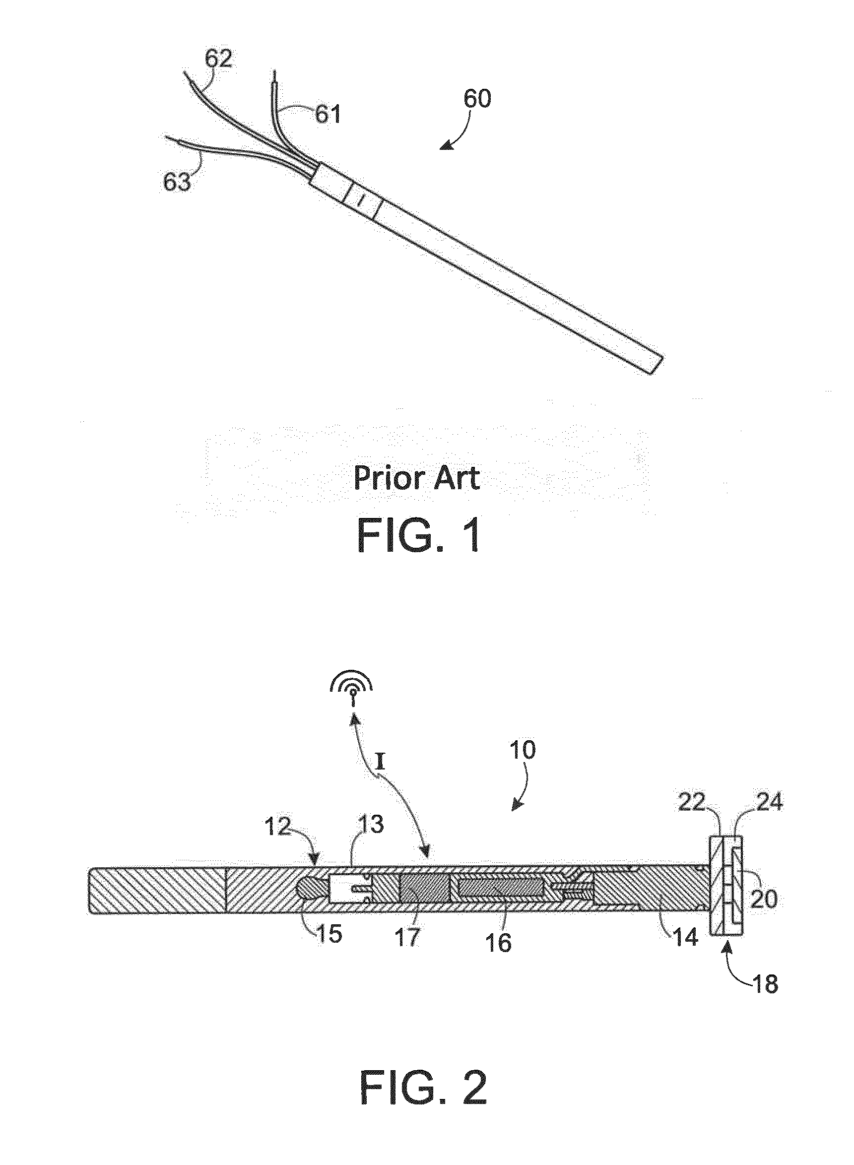
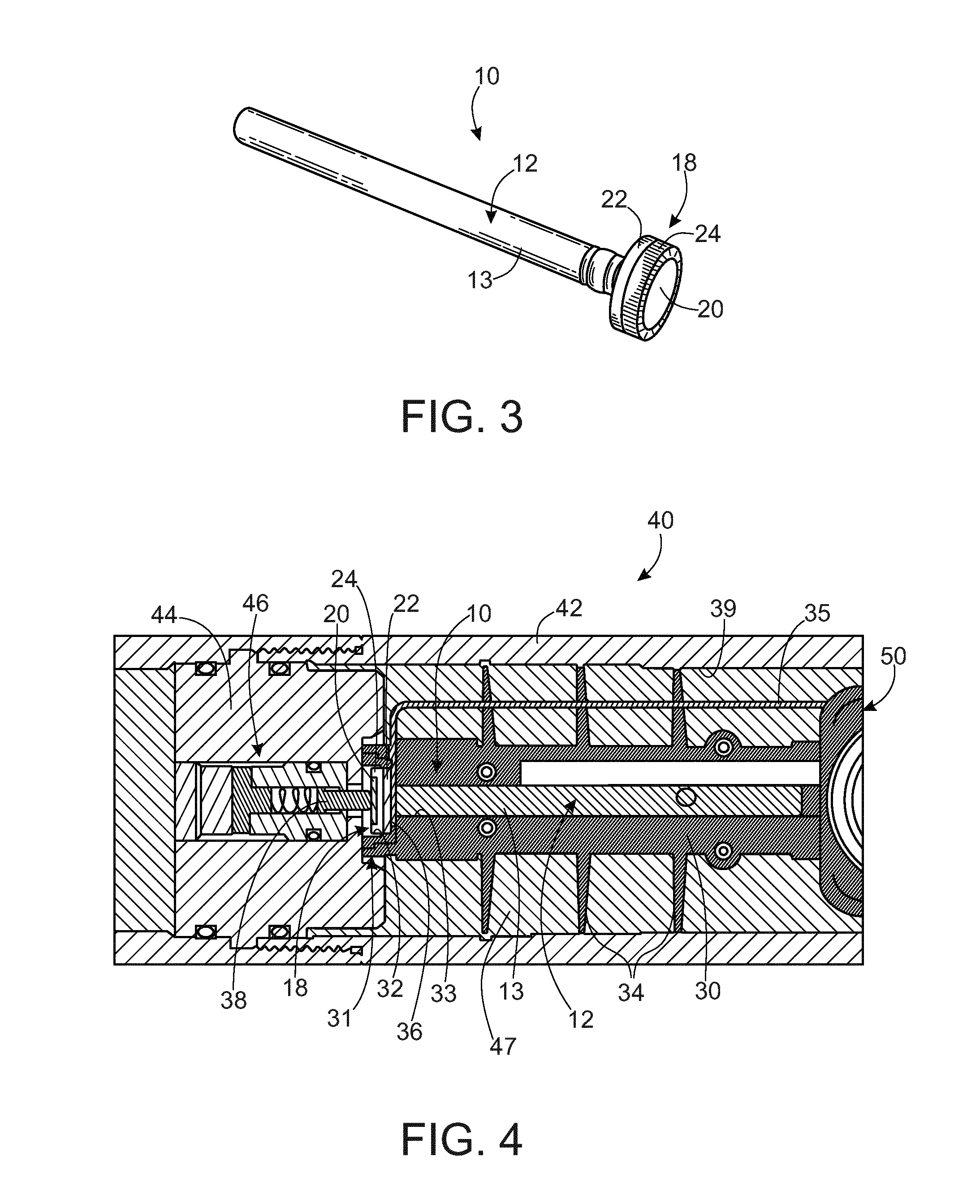
[0019]In an embodiment, a detonator assembly is provided that is capable of being positioned or placed into a perforating gun assembly with minimal effort, by means of placement / positioning within a detonator positioning assembly. In an embodiment, the detonator positioning assembly includes the detonator assembly positioned within the detonator positioning assembly, which is positioned within the perforating gun assembly. The detonator assembly electrically contactably forms an electrical connection without the need of manually and physically connecting, cutting or crimping wires as required in a wired electrical connection. Rather, the detonator assembly described herein is a wirelessly-connectable selective detonator assembly.

[0020]In an embodiment, the detonator assembly is par...


PUM


Abstract

According to an aspect, a perforating gun assembly and a detonator assembly is provided. The detonator assembly includes at least a shell, means for selective detonation, and more than one electrically contactable component that is configured for being electrically contactably received by the perforating gun assembly without using a wired electrical connection, but rather forms the electrical connection merely by contact with at least one of the more than one electrically contactable components. A method of assembling the perforating gun assembly including the detonator assembly is also provided.

Description

CROSS-REFERENCE TO RELATED APPLICATIONS[0001]This application claims priority to PCT Application No. PCT / EP2014 / 065752 filed Jul. 22, 2014, which claims priority to German Patent Application No. 102013190227.6 filed Jul. 26, 2013, each of which are incorporated herein by reference in their entirety.FIELD[0002]Devices and methods for selective actuation of wellbore tools are generally described. In particular, devices and methods for selective arming of a detonator assembly of a perforating gun assembly are generally described.BACKGROUND[0003]Hydrocarbons, such as fossil fuels (e.g. oil) and natural gas, are extracted from underground wellbores extending deeply below the surface using complex machinery and explosive devices. Once the wellbore is established by placement of cases after drilling, a perforating gun assembly, or train or string of multiple perforating gun assemblies, are lowered into the wellbore, and positioned adjacent one or more hydrocarbon reservoirs in underground ...

Claims


Application Information

Patent Timeline
IPC IPC(8): E21B43/1185F42C19/12
CPCF42C19/12E21B43/1185E21B43/11F42B3/10
Inventor EITSCHBERGER, CHRISTIANPREISS, FRANK, HARONSCHARF, THILOMCNELIS, LIAM
Owner DYNAENERGETICS
Why Eureka
Try Eureka