High pressure exposed detonating cord detonator system

Inactive Publication Date: 2005-08-25
HALLIBURTON ENERGY SERVICES INC
View PDF41 Cites 54 Cited by
  • Summary
  • Abstract
  • Description
  • Claims
  • Application Information

AI Technical Summary

Benefits of technology

[0010] The present invention provides a detonator system for detonating cord in well operations in which a detonator and its coupling to the detonating cord is protected from the well environment. The system includes a firing head having a sealed detonator chamber for a detonator and a booster charge holder. The charge holder includes a bulkhead separating the detonator chamber from a booster charge. The firing head chamber is sea

Problems solved by technology

The shaped charges will not function proper

Method used


Image

  • High pressure exposed detonating cord detonator system
  • High pressure exposed detonating cord detonator system
  • High pressure exposed detonating cord detonator system

Examples


Embodiment Construction

[0022] In the following description of embodiments, various terms such as “above” and “below” and “up hole” and “down hole” are used to indicate relative position of elements. These terms are used with reference to the normal position of the apparatus when used in a vertical borehole and are not intended to be limiting. In wells which include slanted or horizontal portions, the term up hole or above refers to the direction toward the surface location of the well and down hole or below refers to the direction toward the end of the well farthest from the surface location. It is to be understood that the a system according to the present invention may be inverted in some applications, for example bottom fired systems, and the relative positions of the various elements may therefore be reversed or inverted.

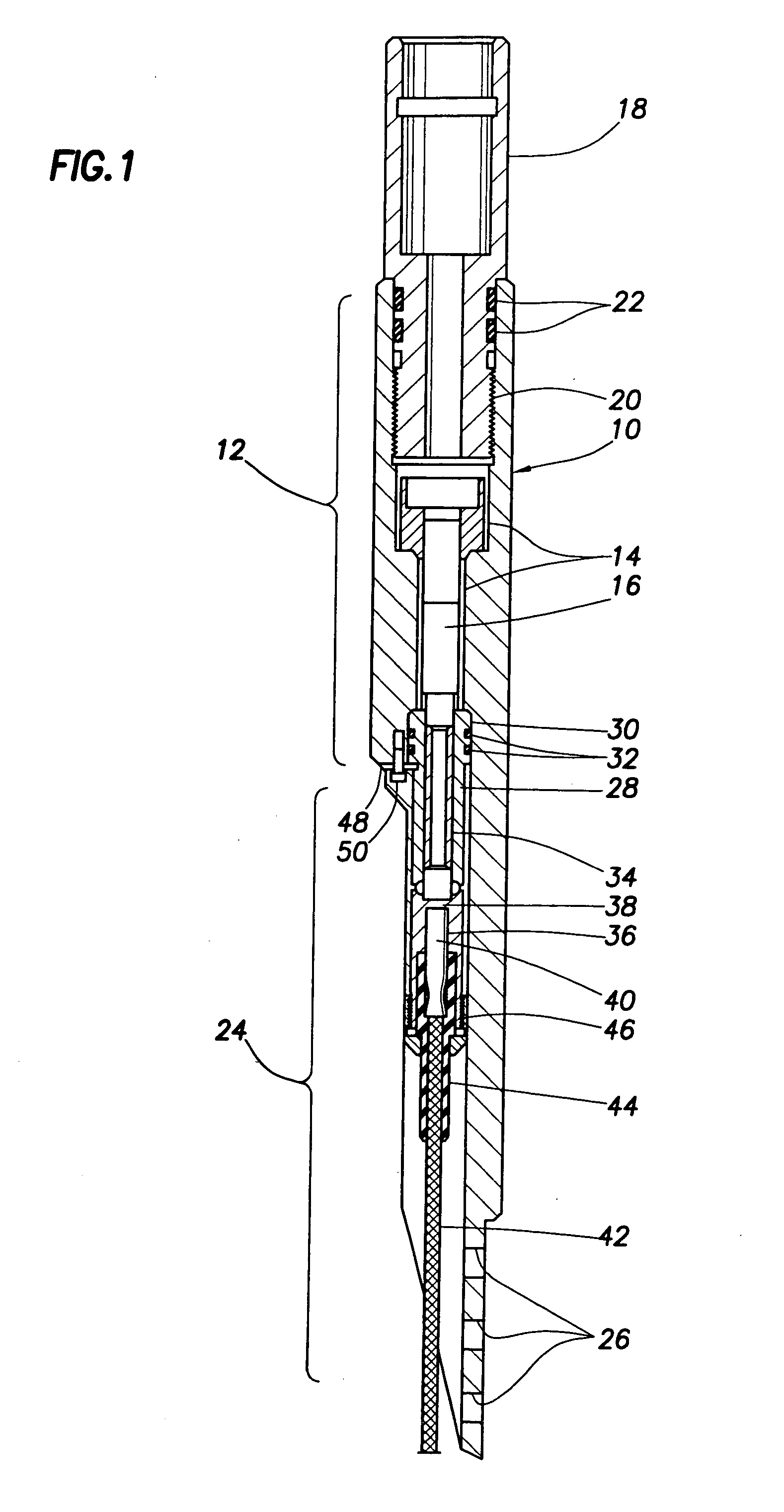
[0023]FIG. 1 provides a cross sectional view of an assembled detonator system according to one embodiment. The primary mechanical component of this embodiment is a firing head 10. Ot...


PUM


Abstract

A detonator system for borehole systems which include detonating cord exposed to borehole fluids, pressures and temperatures. A firing head has a sealed chamber for an electrically fired detonator and has a booster charge holder forming part of the seal. The chamber is sealed by a wire line firing sub and by the booster holder. The charge holder includes a bulkhead separating the detonator chamber from a booster charge chamber and providing part of the detonator chamber seal. The detonator explosive and the booster charge are positioned on opposite sides of the bulkhead so that upon detonation of the detonator, the bulkhead is ruptured and the explosion transfers to the booster charge and from it to the detonating cord. The firing head includes holes for attachment of borehole tools such as perforating guns or back off tools to be fired by the detonating cord.

Description

CROSS-REFERENCE TO RELATED APPLICATIONS [0001] None. STATEMENT REGARDING FEDERALLY SPONSORED RESEARCH OR DEVELOPMENT [0002] Not applicable. REFERENCE TO A MICROFICHE APPENDIX [0003] Not applicable. FIELD OF THE INVENTION [0004] The invention relates to detonating systems, and more particularly to detonators for explosive systems which include detonating cord exposed to hostile environments including high-pressure fluids. BACKGROUND OF THE INVENTION [0005] In oil well perforating operations, it is common practice to use well perforating guns whose explosive components and shaped charges are directly exposed to well bore fluids and pressures. Typically, these explosive components may be carried along a flexible or semi-flexible strip of metallic carrying member and may be locked to the carrying member and affixed through holes bored in the strip, thus directly exposing the shaped charges to the well bore environment. [0006] Perforating guns of this type may be referred to as expendabl...

Claims


Application Information

Patent Timeline
IPC IPC(8): C06C5/06C06C7/00F42B3/00F42D1/04
CPCC06C5/06F42D1/043C06C7/00
Inventor BARTON, JOHN A.WALKER, JERRY L.
Owner HALLIBURTON ENERGY SERVICES INC
Why Eureka
Try Eureka