Vascular implant

a technology of vascular implants and sleeve, which is applied in the field of intravascular implants, can solve the problems of constricted ring member parts, sleeve gaps, and ring members, and achieve the effects of reducing the diameter of the lumen, reducing the ring diameter, and being easy to deploy

Inactive Publication Date: 2007-02-01
NEOVASC MEDICAL LTD
View PDF10 Cites 118 Cited by
  • Summary
  • Abstract
  • Description
  • Claims
  • Application Information

AI Technical Summary

Benefits of technology

[0005] Embodiments of the present invention provide a constricting implant that is simple and inexpensive to manufacture, and can be deployed easily in the blood vessels, as well as in other body passages. The implant comprises a pair of generally-cylindrical ring members, which are fixed to a tubular sleeve so as to define a lumen passing through the ring members and the sleeve. The ring members each comprise a framework made of a resilient material, which can be compressed while the implant is inserted into the desired location in the blood vessel, and then expands either elastically or plastically to roughly the full diameter of the vessel. The sleeve comprises a flexible material, such as a fabric. The ring members are positioned longitudinally along the sleeve so that there is a longitudinal gap in between the two ring members. A constricting element is fitted around the sleeve in this gap so as to reduce the diameter of the lumen in between the two ring members to less than the diameter of the vessel.

Problems solved by technology

The part of the sleeve in the gap between the ring members, however, remains constricted due to the constricting element.

Method used


Image

  • Vascular implant
  • Vascular implant
  • Vascular implant

Examples


Embodiment Construction

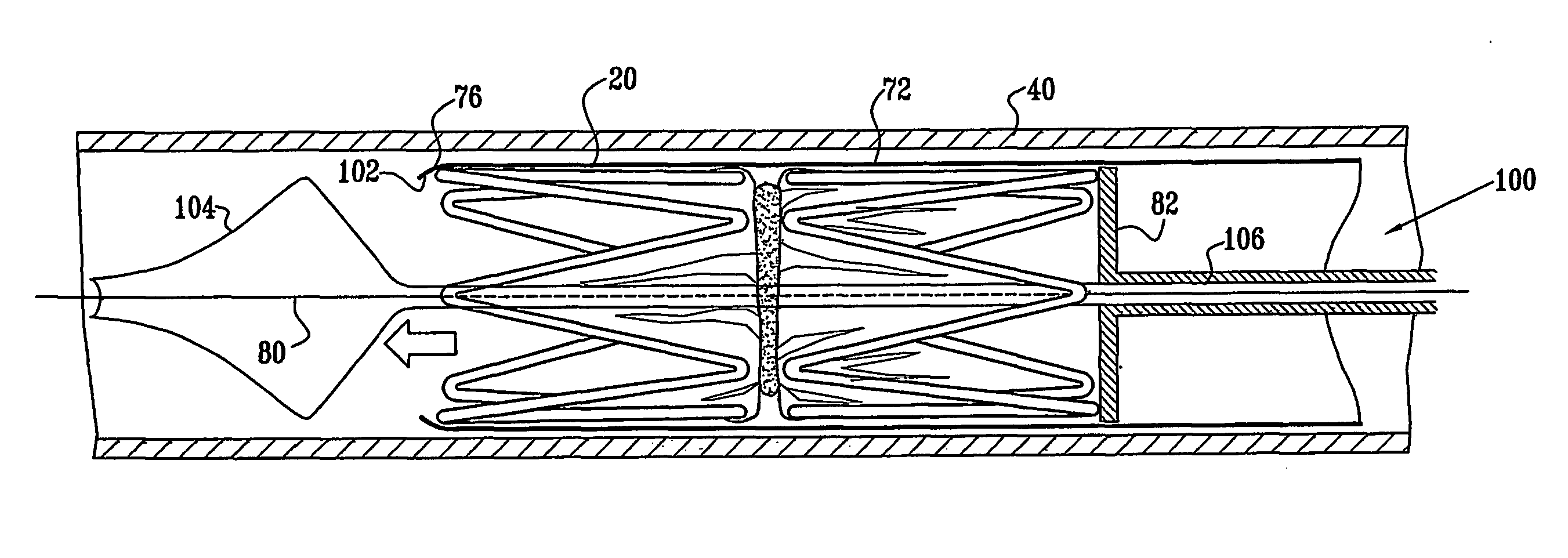
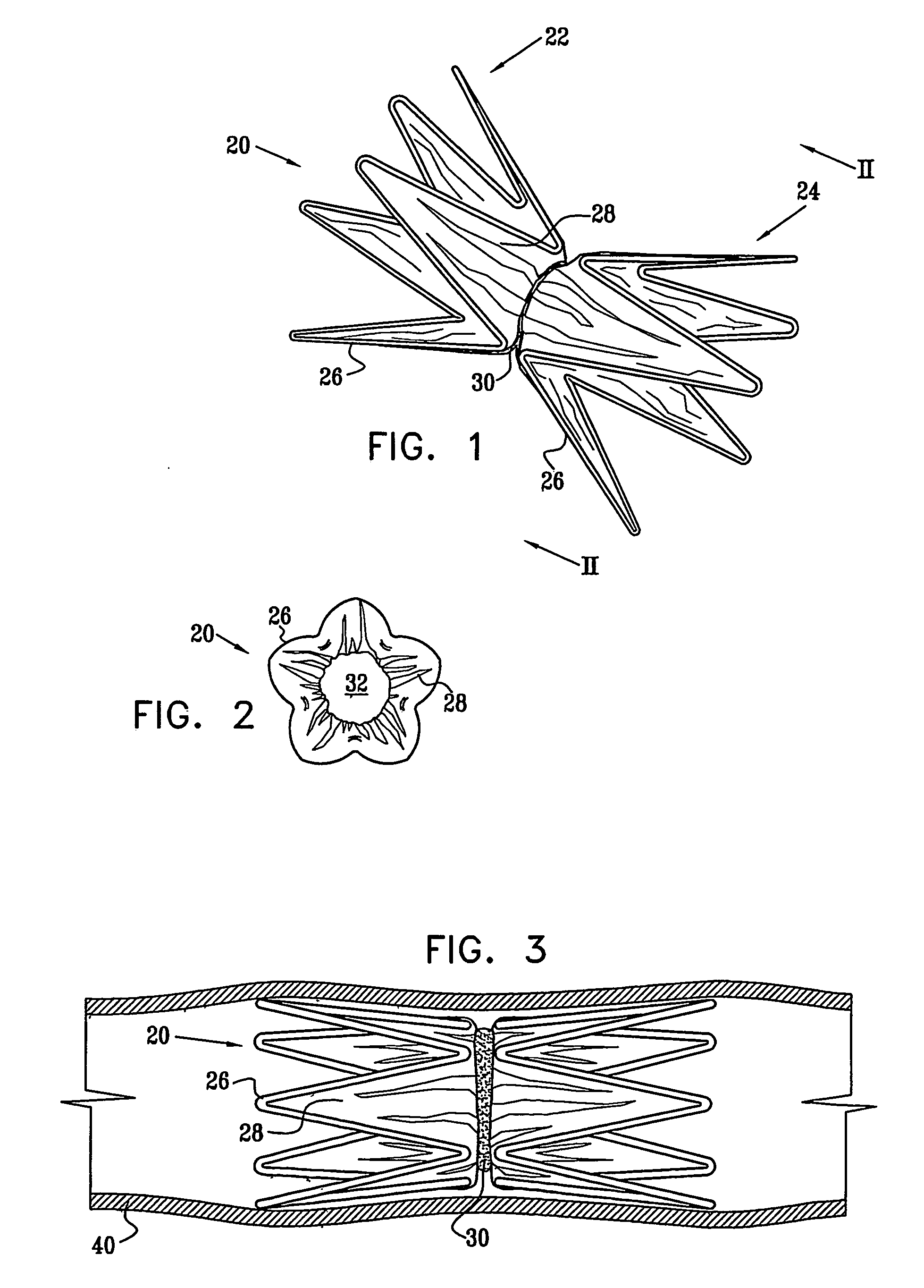
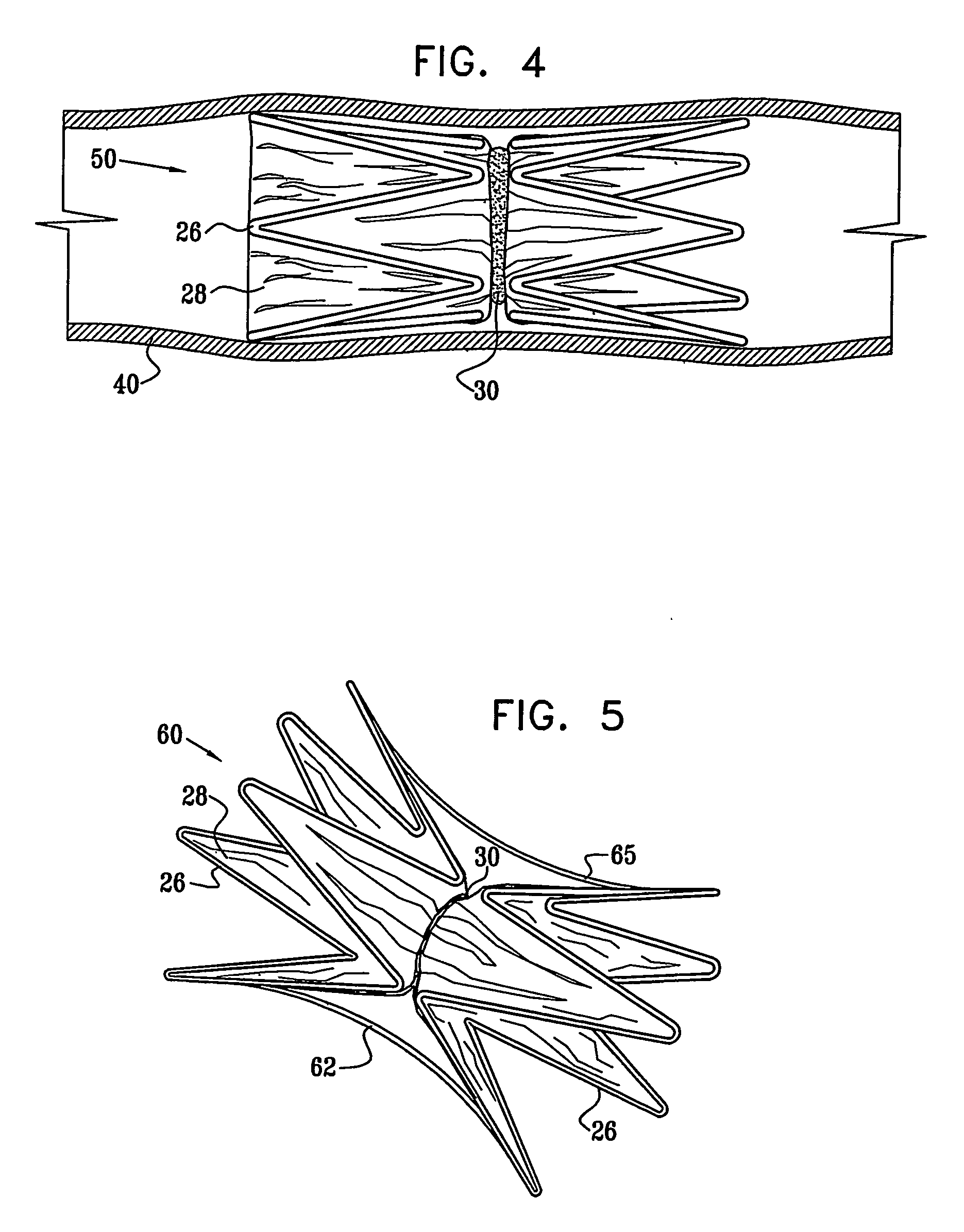
[0068] Reference is now made to FIGS. 1 and 2, which schematically illustrate a device 20 for implantation in a body passage, in accordance with an embodiment of the present invention. FIG. 1 is a pictorial illustration of the device, while FIG. 2 is a cross-sectional view taken along a line II-II in FIG. 1. Device 20 is adapted for use particularly in restricting blood flow through the coronary sinus, as described in the above-mentioned PCT Publication WO 01 / 72239. Alternatively, devices in accordance with the principles of the present invention may be implanted elsewhere in the vascular system, as well as in other body passages. For the sake of simplicity and clarity, however, and not limitation, embodiments of the present invention are described hereinbelow with reference to implantation of flow-constricting devices in blood vessels, such as the coronary sinus.

[0069] Device 20 comprises ring elements 22 and 24, each of which comprises a resilient framework 26. Each framework def...


PUM


Abstract

A medical implant (20) includes first and second ring members (22,24), each including a resilient framework (26) having a generally cylindrical form. A tubular sleeve (28) is fixed to the first and second ring members so as to hold the ring members in mutual longitudinal alignment, thereby defining a lumen (32) passing through the ring members. A constricting element (30) is fit around the sleeve at a location intermediate the first and second ring members so as to reduce a diameter of the lumen at the location.

Description

FIELD OF THE INVENTION [0001] The present invention relates generally to implantable therapeutic devices, and specifically to intravascular implants. BACKGROUND OF THE INVENTION [0002] Stent implants are commonly used in treating arterial stenoses and other unwanted constrictions of body passages. Stents typically comprise a metal coil or mesh. An arterial stent, for example, is threaded through the vascular system to the point of stenosis in an artery. When the stent is in place, it is expanded to force the artery open to the desired diameter. [0003] On the other hand, there are some procedures in which stent implants are required to constrict the diameter of a blood vessel. For example, Ruiz describes an endoluminal stent having adjustable constriction in U.S. Pat. No. 6,120,534, whose disclosure is incorporated herein by reference. The stent comprises a deformable mesh having a conical portion and a constricted region, which forms a flow-limiting constriction. The stent is delive...

Claims


Application Information

Patent Timeline
Patent Type & Authority Applications(United States)
IPC IPC(8): A61F2/84A61F2/86A61B17/122A61B17/128A61FA61F2/00
CPCA61B17/1227A61B17/1285A61F2/07A61F2/95A61F2002/075A61F2002/826A61F2250/0071A61F2/89A61F2220/0058A61F2230/005A61F2230/0054A61F2230/0078A61F2/82A61F2250/0039A61F2/962A61F2/966A61F2002/068
Inventor BEN-MUVHAR, SHMUEL
Owner NEOVASC MEDICAL LTD
Why Eureka
Try Eureka