Deformable ball seat

a ball seat and seat technology, applied in the field of ball seats, can solve the problems of plastic balls that have limited compressive strength and plastic balls that fail, and achieve the effects of increasing the surface area of the seat, reducing the likelihood of force, and enduring higher pressur

Active Publication Date: 2009-02-19
BAKER HUGHES INC
View PDF35 Cites 115 Cited by
  • Summary
  • Abstract
  • Description
  • Claims
  • Application Information

AI Technical Summary

Benefits of technology

[0009]Broadly, ball seats having a housing, a collapsible seat, and a plug element such as a ball are disclosed. Typically, the ball is landed and the conduit is pressurized to a predetermined pressure. Upon pressurization of the conduit so that the ball is pushed into the seat, the seat collapses to provide additional support to the ball as it is being pressurized. In other words, the force of the ball into the seat by the pressure in the tubing or conduit causes the seat to collapse inward toward the centerline (or axis) of the bore of the ball seat and into its collapsed position. In the collapsed position, more surface area of the seat is available to support the ball, thus providing additional support to ball compared to a non-collapsible seat. The collapsed seat may support the ball by increasing the surface area of the seat in direct contact or engagemen

Problems solved by technology

The ball, however, is typically formed out of a plastic material that has limited compressive strength.
This

Method used


Image

  • Deformable ball seat
  • Deformable ball seat
  • Deformable ball seat

Examples


Embodiment Construction

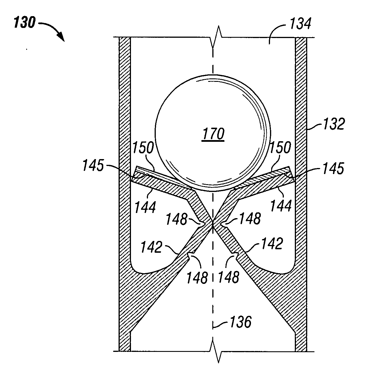
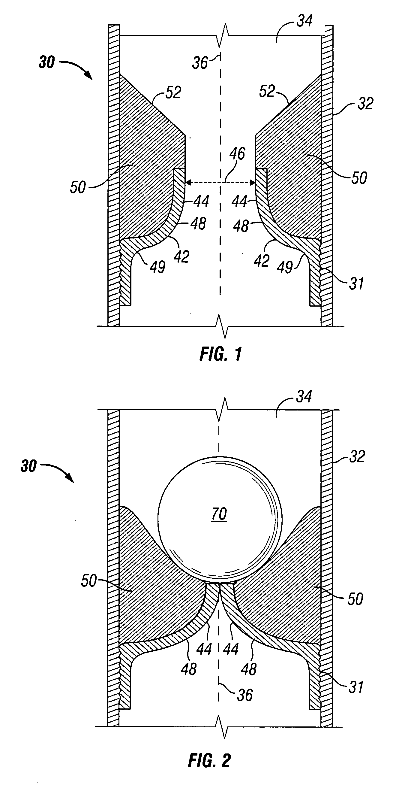
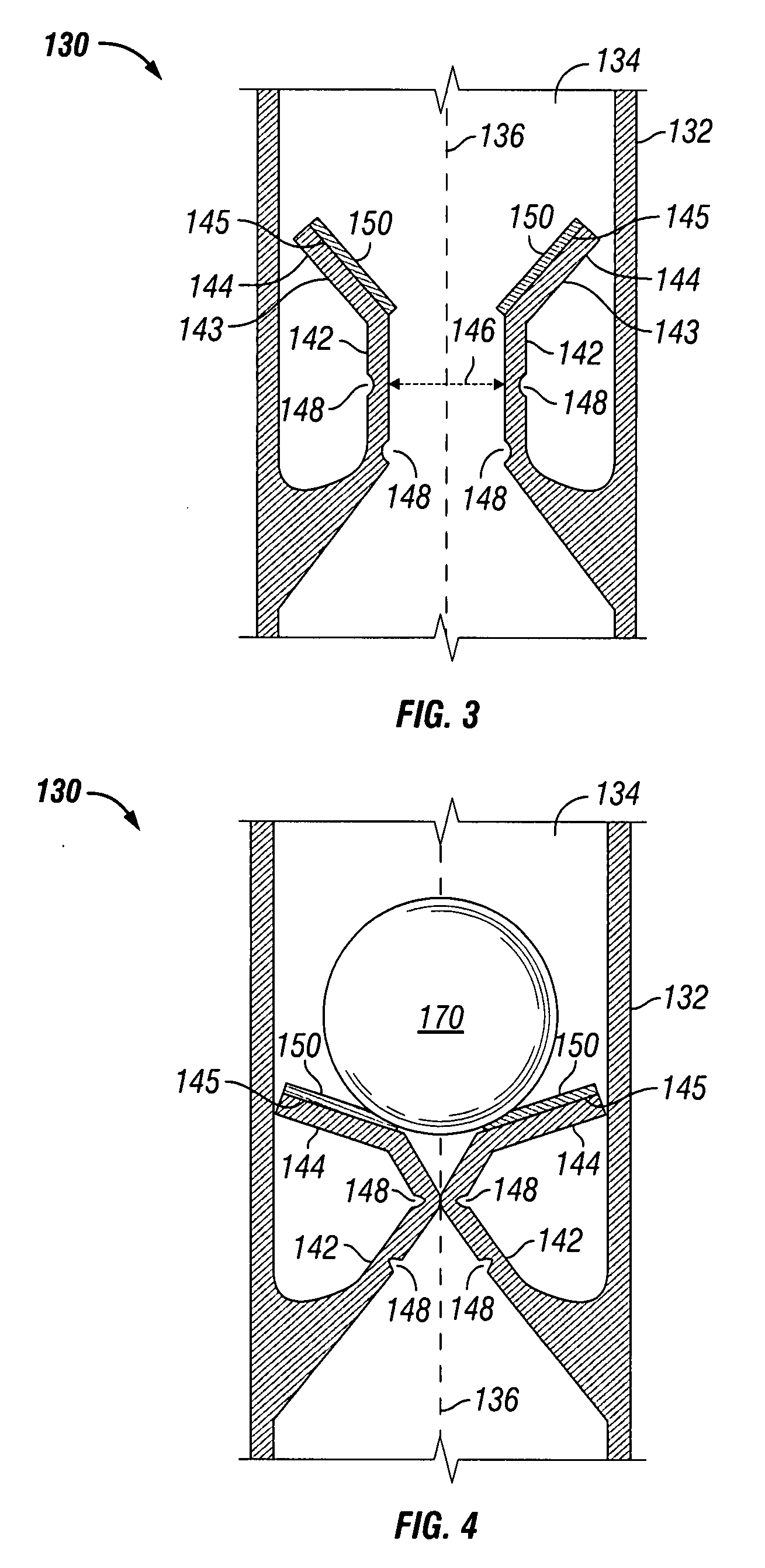
[0022]Referring now to FIGS. 1-2, in one embodiment, ball seat 30 includes a sub or housing 32 having bore 34 defined by an inner wall surface and having axis 36. Attachment members such as threads (not shown) or gripping members (not shown) may be disposed along the outer diameter of each end of housing 32 for securing ball seat 30 into a string of conduit, such as drill pipe or tubing.

[0023]The inner diameter wall surface of housing 34 includes deformable ring 42 that extends inward toward axis 36 to form seat 44 for receiving plug element 70, shown as a ball in FIG. 2. Ring 42 may be secured to the inner wall surface of housing 32 by attachment members such as threads 31 or gripping members (not shown). Alternatively, ring 142 may be formed integral, i.e., part of the same structure, as housing 132 (not shown). Due to ring 42 being deformable, seat 44 is a collapsible seat that, as discussed in greater detail below, bends inwardly when plug element 70 is landed on seat 44. In the...


PUM


Abstract

Apparatuses for restricting fluid flow through a well conduit comprise a housing having a longitudinal bore and a collapsible seat disposed within the bore. The seat has a first position defining a first seat inner diameter when the apparatus is in the run-in position and a second position defining a second seat inner diameter when the apparatus is in the set position. The first seat inner diameter is greater than the second seat inner diameter. A plug element is adapted to be disposed into the bore and landed on the seat to move the seat from the first position to the second position. While in the second position, the seat restricts fluid flow through the bore and provides additional support to the plug member landed on the seat.

Description

BACKGROUND[0001]1. Field of Invention[0002]The present invention is directed to ball seats for use in oil and gas wells and, in particular, to deformable ball seats having a collapsible seat that increases support to the ball.[0003]2. Description of Art[0004]Ball seats are generally known in the art. For example, typical ball seats have a bore or passageway that is restricted by a seat. The ball or drop plug is disposed on the seat, preventing or restricting fluid from flowing through the bore of the ball seat and, thus, isolating the tubing or conduit section in which the ball seat is disposed. As the fluid pressure above the ball or drop plug builds up, the conduit can be pressurized for tubing testing or actuating a tool connected to the ball seat such as setting a packer. Ball seats are also used in cased hole completions, liner hangers, frac systems, flow diverters, and flow control equipment and systems.[0005]Although the terms “ball seat” and “ball” are used herein, it is to ...

Claims


Application Information

Patent Timeline
IPC IPC(8): E21B34/06
CPCE21B34/14Y10T137/791Y10T137/7881E21B33/1208
Inventor KING, JAMES G.RUDDOCK, DAVID B.
Owner BAKER HUGHES INC
Why Eureka
Try Eureka