Flexible 3D Freeform Techniques

a freeform, flexible technology, applied in the direction of additive mnaufacturing with solid and fluid, glass pressing apparatus, butter production, etc., can solve the problems of slow build-up rate, large post-machining cost, poor surface finish, etc., to improve the width of dispensing materials, improve surface finish, and increase manufacturing speed significantly

Active Publication Date: 2016-06-02
NATIONAL TSING HUA UNIVERSITY
View PDF17 Cites 116 Cited by
  • Summary
  • Abstract
  • Description
  • Claims
  • Application Information

AI Technical Summary

Benefits of technology

[0010]The basic principle of the Flexible 3D Freeform technique is to dispense a solidifiable material in a fluid state from a dispensing head onto a base member to build up the material, which solidifies under preset ambient conditions, in a basically continuous fashion according to a predetermined relative movement sequence between the dispensing head and the base member. Based on this principle, this invention comprises a feature of dispensing the solidifiable material along the tangential directions of the surface of the 3D article to be fabricated so that the layered surface feature in existing rapid prototyping processes is eliminated and the surface finish is improved. This invention also comprises a feature of enlarged width of dispensed materials and a corresponding new 3D forming procedure so that fabrication speed can be increased significantly. For these purposes, this invention includes a motion mechanism of multiple degrees of freedom to provide the required relative movement sequence between the dispensing head and the base member. Further, this invention includes a feature of adjusting the width, thickness and flow speed of the dispensed material according to needs from local geometry of a 3D article during the dispensing process. The dispensing head dispenses material in a few basic shapes including ribbon (band), wire and dot. When the geometry of the 3D object to be fabricated allows, wide, ribbon-shaped material can be dispensed so that building speed can be increased. Dispensed materials of wire- and dot-shapes can be applied to build up fine and complex features. Still further, this invention includes a differential molding means, which applies a solid or fluid means in contact with selected positions on dispensed material while it is solidifying, to restrict the flow of and to shape the solidifying material. By this means, good surface finish can be obtained. Curvature in the direction along the width of a ribbon-shaped dispensed material can also be made by this means.

Problems solved by technology

Material build-up by horizontal layers, regardless of the 3D shape to be built, creates inevitable layered (stairs-like) surface feature, resulting in poor surface finish.
Material joining by point scanning is basically “scanning a 3D body by one tiny point”, resulting in slow build-up rate.
When using the SLM technique to make a mold for plastic injection molding, the surface finish can be about 40 um Ra and a machining tolerance of 200˜500 um is generally required, which makes post machining cost significant.
But these methods also increase equipment costs.
However, because the FDM method uses a fixed orifice size to dispense material, the effect of speed Increasing is likely to be limited.
However, the “point scanning” and “layer by layer” issues are not addressed in this approach.
Further, surfaces of built-up parts are usually rough.

Method used


Image

  • Flexible 3D Freeform Techniques
  • Flexible 3D Freeform Techniques
  • Flexible 3D Freeform Techniques

Examples


example 1

Molten Metal as Solidifiable Material, 3D Freeform by a Casting Based Means

1.1 the Material Dispensing System

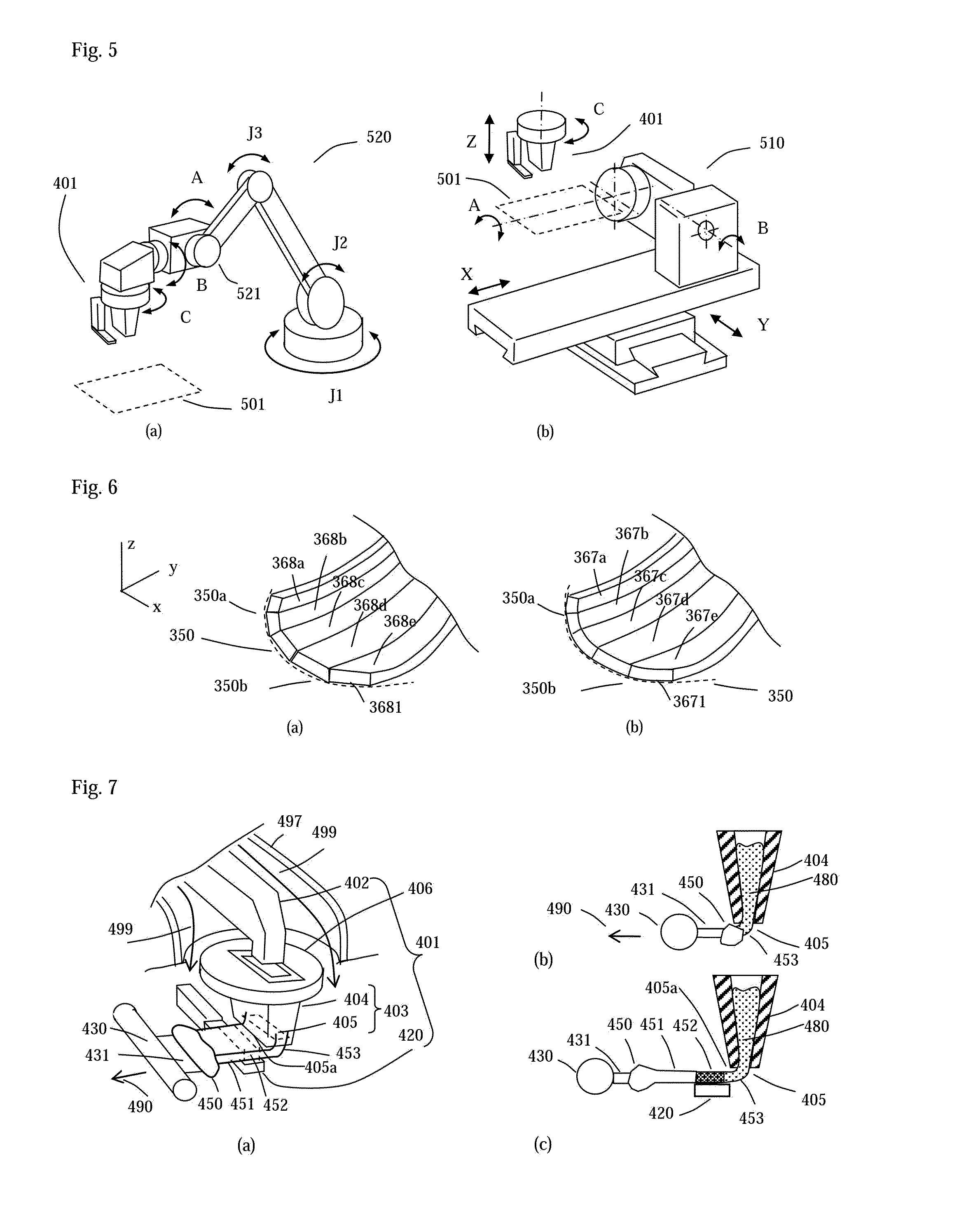
[0067]FIG. 7(a) illustrates an example embodiment of a material dispensing system for metal, which includes a material supply unit 402, a dispensing head 403 and an optional differential molding means 420. FIG. 7(b)-(c) illustrates its cross-sectional views from side. The material supply unit 402, which includes a heating means (such as induction heating or electric arc heating) and a material feeding means (a metal wire powder can be used), sends the material into the dispensing head 403. The dispensing head includes a material cell 404 with an exit 405 at the lower end. A heating means outside of the material cell keeps the metal in molten state 480. A material not reactive to the molten metal is preferred for making the material cell. For example, aluminum oxide, graphite or other high temperature ceramics can be used to contain molten steel. Ceramics can also be used for ...

example 2

Plastics (Polymer Material) as Solidifiable Material, 3D Freeform by an Extrusion-Based Means

2.1 the Material Dispensing System

[0094]The material dispensing system is similar to the system of FIG. 8. Metals, such as aluminum, copper or steel, can be used for the material supply unit 402 and the dispensing head 403. The heating means can heat up the metal and then the metal can heat up the plastic material. Inert gas protection is generally not needed.

2.2 Means for Changing the Width of Dispensed Materials

[0095]The means of changing the width of dispensed materials by using a dispensing head of adjustable exit size and the corresponding basic mechanisms, as depicted in FIGS. 11 and 12, also apply to plastic materials. However, due to differences in properties between plastics and metals, the internal shapes of the material supplying unit and the dispensing head are different.

[0096]In the case of metals, for example in FIG. 12(a), the flow speed of the molten metal 480 along the suppl...

example 3

Molten Metal as Solidifiable Material, 3D Freeform by a Casting-Based Means, with Auxiliary on-Spot Heating

[0103]If the temperature of the base material, which the solidifiable material to be dispensed onto, is too low or its heat sink is too large, the molten metal from the dispensing head may not be able to heat up the previously solidified material within a short time. In this case, the newly dispensed metal could solidify prematurely without good bonding to the base material. To resolve this issue, an auxiliary heating can be applied on spot, i.e. at the targeted dispensing location, to locally preheat the base material. The auxiliary heating source should be able to deliver concentrated heat in a relatively short time. Such a heating source can be constructed based on the principle of a few industrial fusion welding systems, such as gas tungsten-arc welding, plasma-arc welding, or laser welding. FIG. 22 depicts an example system of this invention with an auxiliary arc-based hea...


PUM

PropertyMeasurementUnit
Raaaaaaaaaaa
Raaaaaaaaaaa
relative movementaaaaaaaaaa

Abstract

This invention relates to processes and systems of rapid prototyping and production. Its features includes flexible material deposition along tangential directions of surfaces of a part to be made, thereby eliminating stair-shape surface due to uniform horizontal layer deposition, increasing width of material deposition to increase build up rate, applying the principles of traditional forming/joining processes, such as casting, fusion welding, plastic extrusion and injection molding in the fabrication process so that various industrial materials can be processed, applying comparatively low cost heating sources, such as induction heating and arc-heating. Additional features include varying width and size of material deposition in accordance with geometry to be formed and applying a differential molding means for improved shape formation and surface finishing.

Description

CROSS-REFERENCE TO RELATED APPLICATIONS AND OTHER DOCUMENTS[0001]This application claims the benefit of prior U.S. provisional application No. 62 / 085,509, filed 29 Nov. 2014, the contents of which are incorporated herein by reference.BACKGROUND OF THE INVENTION[0002]This invention relates to systems and methods of rapid prototyping and production (or called additive manufacturing or 3D printing). Especially, this invention relates to fabricating 3D prototypes, articles, components and molds at improved surface finish and increased speed.[0003]Existing major rapid prototyping (also known as additive manufacturing or 3D printing) techniques include methods such as SLM (Selective Laser Melting) for making metal parts (for examples, EOS M400, referring to http: / / www.eos.info / systems_solutions / metal / systems_equipment / eos_m_400, 3D Systems SPro 250, see http: / / production3dprinters.com / sites / production3dprinters.com / files / downloads / sPro-125-250-SLM-Direct-Metal.pdf, or Renishaw AM250, refe...

Claims


Application Information

Patent Timeline
Patent Type & Authority Applications(United States)
IPC IPC(8): B22D23/00B23K9/04C03B19/00B29C67/00
CPCB22D23/003B29C67/0066B29C67/0055B29C67/0081B33Y30/00B23K9/04C03B19/00B33Y10/00B33Y50/02B29C67/0088C03B19/025B29C64/135B29C64/165B29C64/118B29C64/393B29C64/106B29C64/386
Inventor TSAO, CHE-CHIH
Owner NATIONAL TSING HUA UNIVERSITY
Why Eureka
Try Eureka