Method and system for additive-ablative fabrication

a technology of additiveablative and manufacturing method, applied in the field of solid free form fabrication (sff), can solve the problems of oxygen inhibition, difficulty in reducing the resolution of viscous material with a resolution below 40 m, and difficulty in reducing the resolution of viscous material, so as to achieve the effect of preventing oxygen inhibition, preventing oxygen inhibition, and preventing the curing process

Active Publication Date: 2018-03-15
IO TECH GRP LTD
View PDF0 Cites 18 Cited by
  • Summary
  • Abstract
  • Description
  • Claims
  • Application Information

AI Technical Summary

Benefits of technology

[0070]In yet another feature, a method of solid free form fabrication using the printer pressing assembly of the present disclosure may include providing the press strop with a first press stop and a second press stop. Further, the method may include elevating the first press stop to a different height relative to the second press stop so as to provide an inclined engagement surface that engages the abutment surface of the press such that the press is oriented at angle with respect to the support surface. Further, the method may include progressively lowering an elevation of one of the first press stop and the second press stop such that the first material is progressively pressed by the press in a direction from one end of the support surface towards another end of the support surface at which the one of the first press stop and second press stop is lowered. Thereby, eliminating air bubbles within the first material as the contact surface of the press becomes oriented horizontal to the support surface.

Problems solved by technology

It is further noted that in the conventional art printing viscous material with a resolution below 40 μm is relatively complex.
Additionally, the conventional art has a problem of oxygen inhibition that may occur in, for example, the curing of a monomer.
In this regard, oxygen inhibition may hinder significantly or can even stop the curing process.
For this reason, it is relatively complex to cure plastic in atmospheric environment; and therefore, a special inert as environment is required.
The end result may range from reduced coating properties to uncured, liquid surfaces on the coating.
The aforementioned problem is even more pronounced in low intensity curing processes, such as UV LED or UVA cure, which frequently result in sticky, uncured surfaces.

Method used


Image

  • Method and system for additive-ablative fabrication
  • Method and system for additive-ablative fabrication
  • Method and system for additive-ablative fabrication

Examples


examples

[0181]Reference is now made to the following examples, which together with the above descriptions illustrate some embodiments of the present disclosure in a non limiting fashion.

Exemplified SFF Process

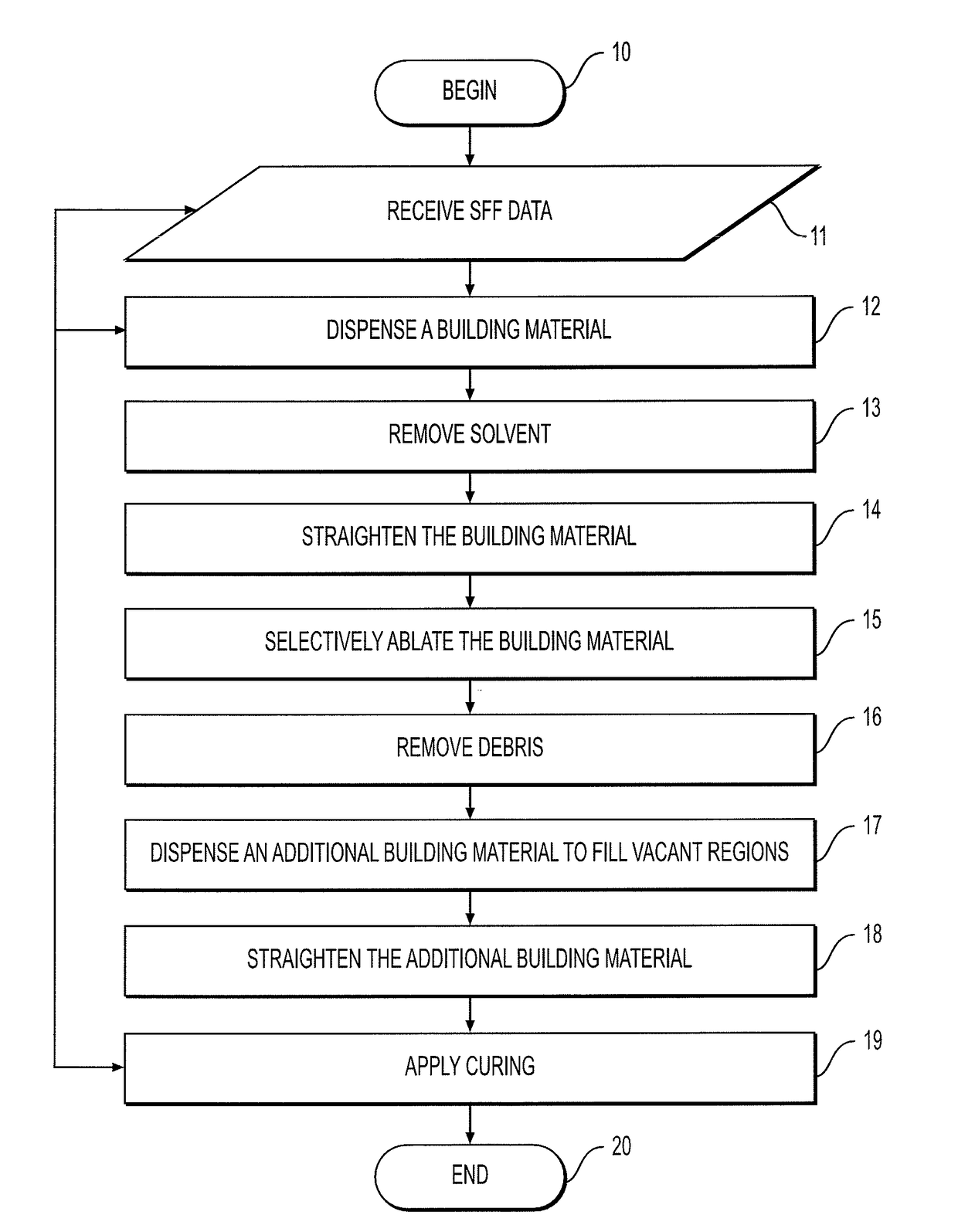
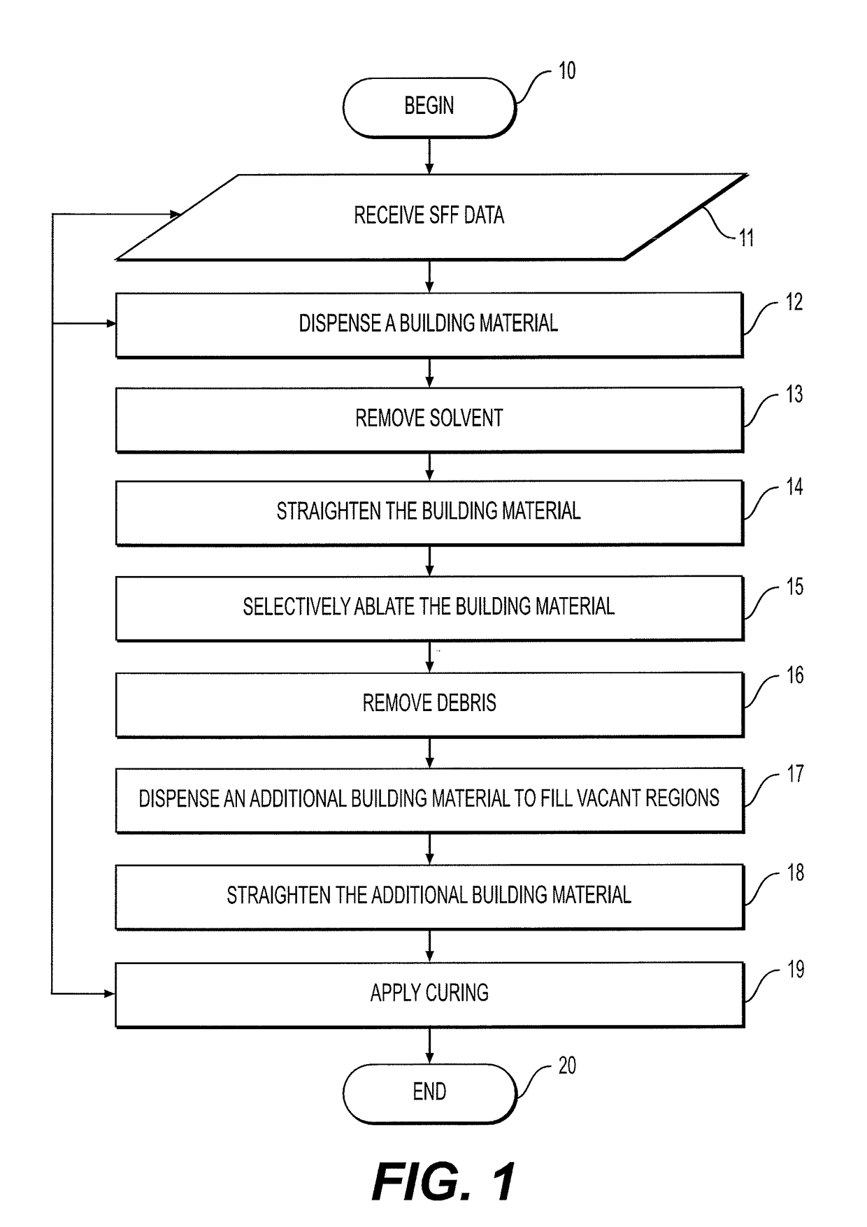
[0182]FIG. 6 is a flow chart diagram describing a representative example of an SFF process, according to some embodiments of the present disclosure. A layer thickness is defined by vertical drive 94. Then, a material is dispensed, following by an optional drying operation. Stagnating is then applied, for example, by a blade squeegee. Thereafter, the leveled (or straightened) material is ablated to form a two-dimensional pattern. Optionally, the material is then cured or sintered. An additional straightening operation can optionally executed following the curing or sintering. The process then loops to the first block for defining the next layer.

Exemplified Placement of Foreign Element

[0183]FIG. 7 is a flow chart diagram describing a representative example of a process for combining a fo...


PUM

PropertyMeasurementUnit
thicknessaaaaaaaaaa
thicknessaaaaaaaaaa
thicknessaaaaaaaaaa

Abstract

A method of solid free form fabrication (SFF) is disclosed. The method comprises: receiving SFF data collectively pertaining to a three-dimensional shape of the object and comprising a plurality of slice data each defining a layer of the object. The method also comprises, for each of at least a few of the layers, dispensing a building material on a receiving medium, straightening the building material, and selectively ablating the building material according to respective slice data.

Description

CROSS REFERENCE TO RELATED APPLICATION[0001]The present application claims the benefit of U.S. Provisional Application No. 67 / 194,849 filed on Sep. 15 20l6. the disclosure of which is expressly incorporated by reference herein in its entirety.FIELD OF THE INVENTION[0002]The present disclosure, in some embodiments thereof, relates to solid free form fabrication (SFF) and, more particularly, but not exclusively, to a method, system and apparatus for SFF by an additive-ablative process.BACKGROUND OF THE INVENTION[0003]SFF is typically used in design-related fields where it is used for visualization, demonstration and mechanical prototyping. Thus, in three-dimensional fabrication facilitates rapid fabrication of functioning prototypes with minimal investment in tooling and labor may be employed. Such rapid prototyping shortens the product development cycle and improves the design process by providing rapid and effective feedback to the designer. Three-dimensional fabrication can also be...

Claims


Application Information

Patent Timeline
Patent Type & Authority Applications(United States)
IPC IPC(8): B29C64/393B29C64/379B29C64/209B29C64/277B29C64/268
CPCB29C64/393B29C64/379B29C64/209B29C64/277B29C64/268B22F3/008B33Y10/00B33Y30/00G05B19/4099G05B2219/49016G05B2219/49021B29C64/30Y02P90/02B22F10/73B22F10/10B22F12/63B22F12/53Y02P10/25B29C64/40B29C64/106B29C2035/0838B29C64/118B29C64/112B29C64/165B23K26/402
Inventor ZENOU, MICHAELGILAN, ZIV
Owner IO TECH GRP LTD
Why Eureka
Try Eureka