Acceleration of stereolithography

a stereolithography and acceleration technology, applied in the field of additives, can solve the problems of needing to submerge, use additional mechanical elements, extreme care, etc., and achieve the effects of enhancing the photopolymerization cure chemistry, reducing the viscosity of the liquid, and facilitating the re-filling of polymerizable liquid

Active Publication Date: 2018-05-22
CARBON INC
View PDF32 Cites 20 Cited by
  • Summary
  • Abstract
  • Description
  • Claims
  • Application Information

AI Technical Summary

Benefits of technology

[0012]In some embodiments, the speed of fabrication of the three-dimensional object is increased by at least 20, 40, or 60 percent, or in some embodiments at least doubled or tripled (up to an increase in fabrication speed by a multiple of 20, 40, 60 or 100), as compared to the speed of fabrication of the three-dimensional object when the Lewis acid is not included in the polymerizable liquid.
[0020]The method may further comprise heating the polymerizable liquid as it is supplied to the build region and / or within the build region (e.g., by an amount as given in the Examples below) to reduce the viscosity thereof in the build region (e.g., by an amount as given in the Examples below).
[0029]Advancing can be carried out at any suitable cumulative or average rate. The rate may be constant or variable (e.g., a predetermined variable pattern, or adjusted by control factors as discussed below). Advancing may be carried out continuously rather than in interrupted “steps”. In some embodiments the advancing step may be carried out at a rate of at least 0.1, 1, 10, 100 or 100 microns per second, or more, up to, for example, the point at which the heat of the polymerization reaction reaches the degradation temperature of the polymerized reaction product. As noted above, advancing may be in an uninterrupted manner, e.g., without the need for forming a complete gap between the build plate or polymerizable liquid, on the one hand, and the carrier or object on the other, to facilitate re-filling of polymerizable liquid between steps.
[0030]In some embodiments, the polymerizable liquid is heated during the filling step, e.g., heated sufficiently to reduce the viscosity thereof, and in some embodiments, enhancing the photopolymerization cure chemistry, and thereby increase the speed or rate at which steps (b) through (d) may be repeated. In some embodiments, the polymerizable liquid is cooled, such as with a peltier cooler, contacting to a heat sink, contacting with a chilling element containing a chilled liquid circulated therethrough, contacting to or circulating through a heat exchanger, etc., or combinations thereof, to dissipate the heat derived from the photopolymerization process in adjacent regions in the build object.

Problems solved by technology

A disadvantage of such “top down” techniques is the need to submerge the growing object in a (potentially deep) pool of liquid resin and reconstitute a precise overlayer of liquid resin.
While such “bottom up” techniques hold the potential to eliminate the need for a deep well in which the object is submerged by instead lifting the object out of a relatively shallow well or pool, a problem with such “bottom up” fabrication techniques, as commercially implemented, is that extreme care must be taken, and additional mechanical elements employed, when separating the solidified layer from the bottom plate due to physical and chemical interactions therebetween.
Such approaches introduce a mechanical step that may complicate the apparatus, slow the method, and / or potentially distort the end product.

Method used


Image

  • Acceleration of stereolithography
  • Acceleration of stereolithography
  • Acceleration of stereolithography

Examples


example 1

Inhibitor Transfer to Build Surface from a Separate Feed Surface

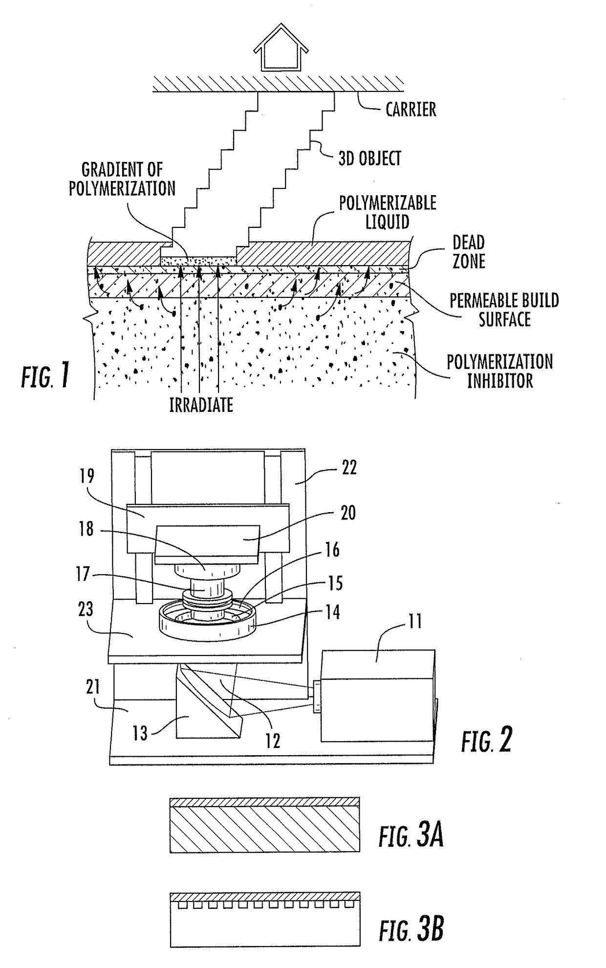
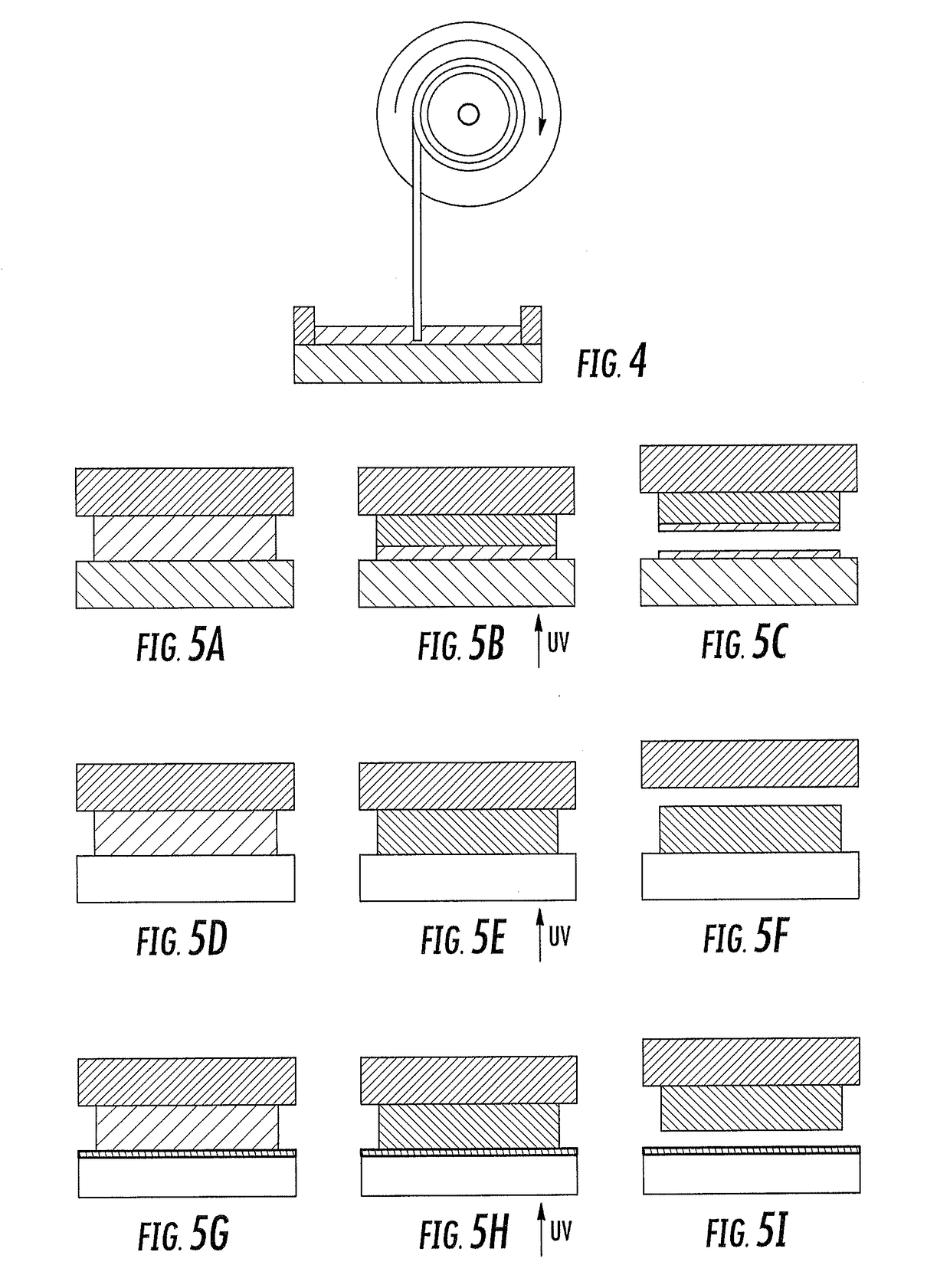
[0161]A drop of ultraviolet (UV) curable adhesive was placed on a metal plate and covered with 10 mm thick plate of TEFLON® AF fluoropolymer (a amorphous, glassy polymer) as shown in FIG. 5A. UV radiation was supplied to the adhesive from the side of Teflon AF as shown in FIG. 5B. After UV exposure the two plates were separated. It was found that no force was required to separate the two plates. Upon examination of the samples it was discovered that the adhesive was cured only next to the metal plate, and that a thin film of uncured adhesive was present on the Teflon AF fluoropolymer plate and also on the cured portion of the adhesive as shown in FIG. 5C.

[0162]Two controlled experiments were also performed where clean glass (FIGS. 5D-5F) and also glass treated with release layer (FIGS. 5G-5I) was used. It was confirmed that considerable force was needed to separate clean glass from the metal and it was found that adhesi...

example 2

Inhibitor Transfer Through Build Plate to Build Surface

[0164]Samples 1 and 2 were prepared in a similar manner wherein a drop of UV curable adhesive was placed on a metal plate and covered with 10 mm thick plate of TEFLON® AF fluoropolymer as shown in FIG. 6A. Both samples were exposed to a nitrogen environment to eliminate any presence of oxygen as shown in FIG. 6B. Next both samples were brought into a standard atmosphere environment and Sample 1 was immediately exposed to UV radiation while Sample 2 was exposed to UV radiation 10 minutes after being in the atmosphere environment. Both samples were exposed to the same amount of UV radiation as shown in FIG. 6C and FIG. 6E. Upon examination of the samples after UV exposure it was discovered that the adhesive was cured completely in Sample 1 as shown in FIG. 6D and only next to the metal plate in Sample 2 as shown in FIG. 6F. A thin film of uncured adhesive was present on the Teflon AF fluoropolymer plate and also on the cured porti...

example 3

Increasing Fabrication Rate: Pressure

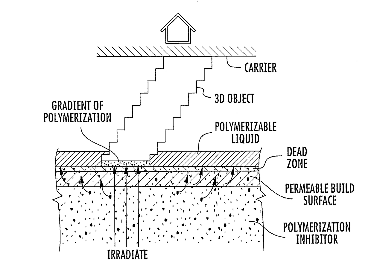
[0165]A highly oxygen permeable, and UV transparent material is used as the bottom of a chamber filled with photocurable resin in a device of the invention. During construction, the top of an object is attached to a support plate which is moved up at a substantially constant speed while the bottom portion of the object is constantly being formed just above the bottom of the chamber. The gap between the bottom of the object and the bottom of the chamber is always filled with resin. As the object is being formed and advanced, the resin in the gap is constantly replenished with supply resin contained in the chamber.

[0166]The speed of the object's formation depends on the viscosity of the resin η, atmospheric pressure P, the height of the gap between the object and the bottom of the chamber h, and the linear dimension L of the object's bottom surface. Simple calculations are performed to estimate this speed using the theory of viscous flow between tw...


PUM

PropertyMeasurementUnit
thicknessaaaaaaaaaa
timeaaaaaaaaaa
wavelengthaaaaaaaaaa

Abstract

A method of forming a three-dimensional object by bottom-up three-dimensional fabrication by irradiating a polymerizable liquid to produce the three-dimensional object, is described. In the method: (i) a Lewis acid or an oxidizable tin salt (e.g., stannous octoate) is included in said polymerizable liquid in an amount effective to accelerate the formation of said three-dimensional object during said fabrication; and / or (ii) the three-dimensional object is irradiated after forming to further polymerize unpolymerized material remaining in the three-dimensional object.

Description

RELATED APPLICATIONS[0001]This application claims the benefit of U.S. provisional patent application Ser. No. 62 / 036,394, filed Aug. 12, 2014, the disclosure of which is incorporated by reference herein in its entirety.FIELD OF THE INVENTION[0002]The present invention concerns additives and methods of speeding the fabrication of the three-dimensional objects in additive manufacturing techniques such as “bottom up” three dimensional fabrication (sometimes generally referred to as stereolithography).BACKGROUND OF THE INVENTION[0003]In conventional additive or three-dimensional fabrication techniques, construction of a three-dimensional object is performed in a step-wise or layer-by-layer manner. In particular, layer formation is performed through solidification of photo curable resin under the action of visible or UV light irradiation. Two techniques are known: one in which new layers are formed at the top surface of the growing object; the other in which new layers are formed at the ...

Claims


Application Information

Patent Timeline
Patent Type & Authority Patents(United States)
IPC IPC(8): C08F2/48C08F2/50B29C67/00B33Y10/00B33Y70/00B29C64/135B29C64/205B29C64/129B29C64/245B29C64/124B29K105/00
CPCB29C64/129B29C64/135B29C64/205B29C64/245B29C64/124B33Y70/00B33Y10/00B29K2105/0002B29K2105/0005B29K2105/0058
Inventor ROLLAND, JASON P.DESIMONE, JOSEPH M.
Owner CARBON INC
Why Eureka
Try Eureka