Wireless detonator assemblies, corresponding blasting apparatuses, and methods of blasting

a detonator and assembly technology, applied in the direction of electric fuzes, lighting and heating apparatus, ammunition fuzes, etc., can solve the problems of circuitry itself presenting safety issues, unintentional actuation of detonator base charges, and labour-intensive establishment of blasting arrangements

Active Publication Date: 2010-10-12
ORICA EXPLOSIVES TECH PTY LTD
View PDF88 Cites 56 Cited by
  • Summary
  • Abstract
  • Description
  • Claims
  • Application Information

AI Technical Summary

Benefits of technology

[0011]It is another object of the present invention, at least in preferred embodiments, to provide a detonator assembly in which the risk of inadvertent activation of the firing circuit, and actuation of the base charge is essentially eliminated.
[0032]transmitting at least one command signal from said at least one blasting machine to cause each detonator assembly to discharge said electrical power into said firing circuit, thereby causing actuation of each base charge.

Problems solved by technology

The establishment of the blasting arrangement, and the positioning of explosive charges, is often labour intensive and highly dependent upon the accuracy and conscientiousness of the blast operator.
However, this programmable circuitry can itself present safety issues.
For example, the power supply for the programmable circuitry may inadvertently trigger the firing circuitry of the detonator, resulting in unintentional actuation of the detonator base charge.
However, the power source in the control unit that enables the communication is too small to risk inadvertent detonator actuation.
However, such systems present formidable technological challenges, many of which remain unresolved.
One obstacle to automation is the difficulty of robotic manipulation and handling of detonators at the blast site, particularly where the detonators require tieing-in or other forms of hook up to electrical wires, shock tubes or the like.
In addition, manual set up and tieing in of detonators via physical connections is very labour intensive, requiring significant time of blast operator time.
Nonetheless, existing wireless blasting systems still present significant safety concerns, and improvements are required if wireless systems are to become a viable alternative to traditional “wired” blasting systems.

Method used


Image

  • Wireless detonator assemblies, corresponding blasting apparatuses, and methods of blasting
  • Wireless detonator assemblies, corresponding blasting apparatuses, and methods of blasting
  • Wireless detonator assemblies, corresponding blasting apparatuses, and methods of blasting

Examples


Embodiment Construction

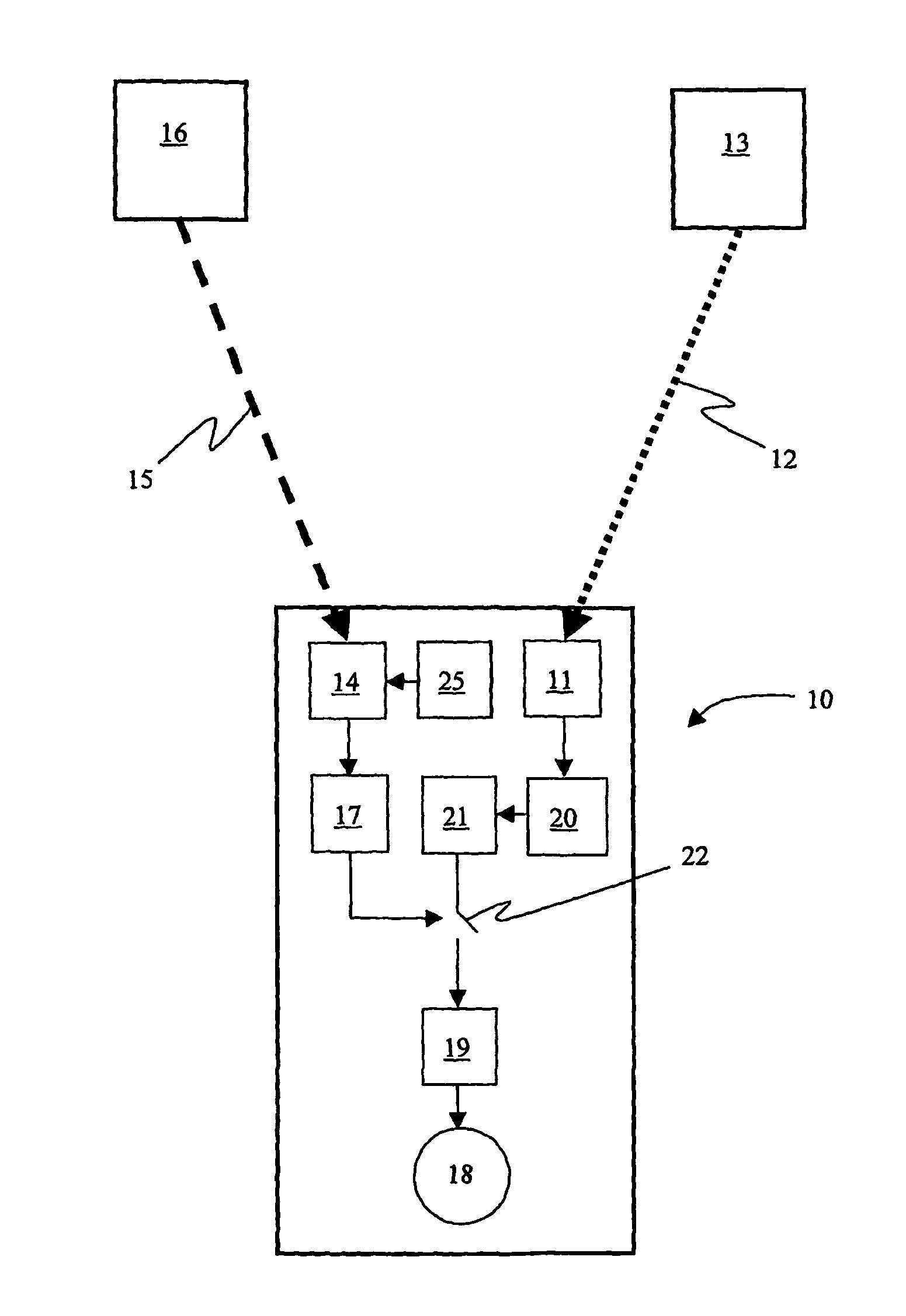
[0067]Wireless blasting systems circumvent the need for complex wiring systems at the blast site, and associated risks of improper placement, association and connection of the components of the blasting system. However, the development of wireless communications systems for blasting operations has presented significant new challenges for the industry, including new safety issues.

[0068]Through careful investigation, the inventors have determined that the wireless detonators and blasting systems of the prior art are problematic with regard to inadvertent or accidental actuation of the detonators. Rapid and accurate communication between a blasting machine, and associated detonators represents a difficult challenge, regardless of the nature of the wireless communication systems. One of the most important signals that must be properly and accurately processed by a wireless detonator is the signal to FIRE. Failure of the communication systems to fire detonators on command can result in a...


PUM


Abstract

A wireless or partially wireless detonator assembly (10) and corresponding blasting apparatus, that may be “powered Up” by a remote source of power (13) that is entirely distinct from the energy used for general command signal communications (16). In one embodiment, the detonator assembly (10) may include an active power source (25) with sufficient power for communications, but insufficient power to cause intentional or inadvertent actuation of the detonator (10).

Description

TECHNICAL FIELD[0001]This invention relates to the field of apparatuses and methods for improving the safety of detonators, detonator assemblies, and blasting apparatuses employing such detonators and detonator assemblies. In particular, the invention relates to assemblies, apparatuses and methods for controlling and firing detonators that are free or substantially free of physical connection to corresponding blasting machines via, for example, electronic wires or shock tube.BACKGROUND ART[0002]In mining operations, the efficient fragmentation and breaking of rock by means of explosive charges demands considerable skill and expertise. In most mining operations explosive charges are planted in appropriate quantities at calculated positions in the rock. The explosive charges are then actuated via detonators with predetermined time delays, thereby providing the desired pattern of blasting and rock fragmentation. Typically, signals are transmitted to the detonators via non-electric syst...

Claims


Application Information

Patent Timeline
Patent Type & Authority Patents(United States)
IPC IPC(8): F42C15/40
CPCF42B3/113F42B3/121F42C15/42F42D1/045
Inventor CHAN, SEK KWANSTEWART, RONALD F.BAMPFIELD, HOWARD A.
Owner ORICA EXPLOSIVES TECH PTY LTD
Why Eureka
Try Eureka