Liquid ejection head and liquid ejection method
a liquid ejection and liquid ejection technology, applied in the direction of printing, inking apparatus, etc., can solve the problems of degrading the print quality, affecting the air resistance more easily, and early disconnection, and achieve the effect of reducing the deviation of the dot landing position
- Summary
- Abstract
- Description
- Claims
- Application Information
AI Technical Summary
Benefits of technology
Problems solved by technology
Method used
Image
Examples
first embodiment
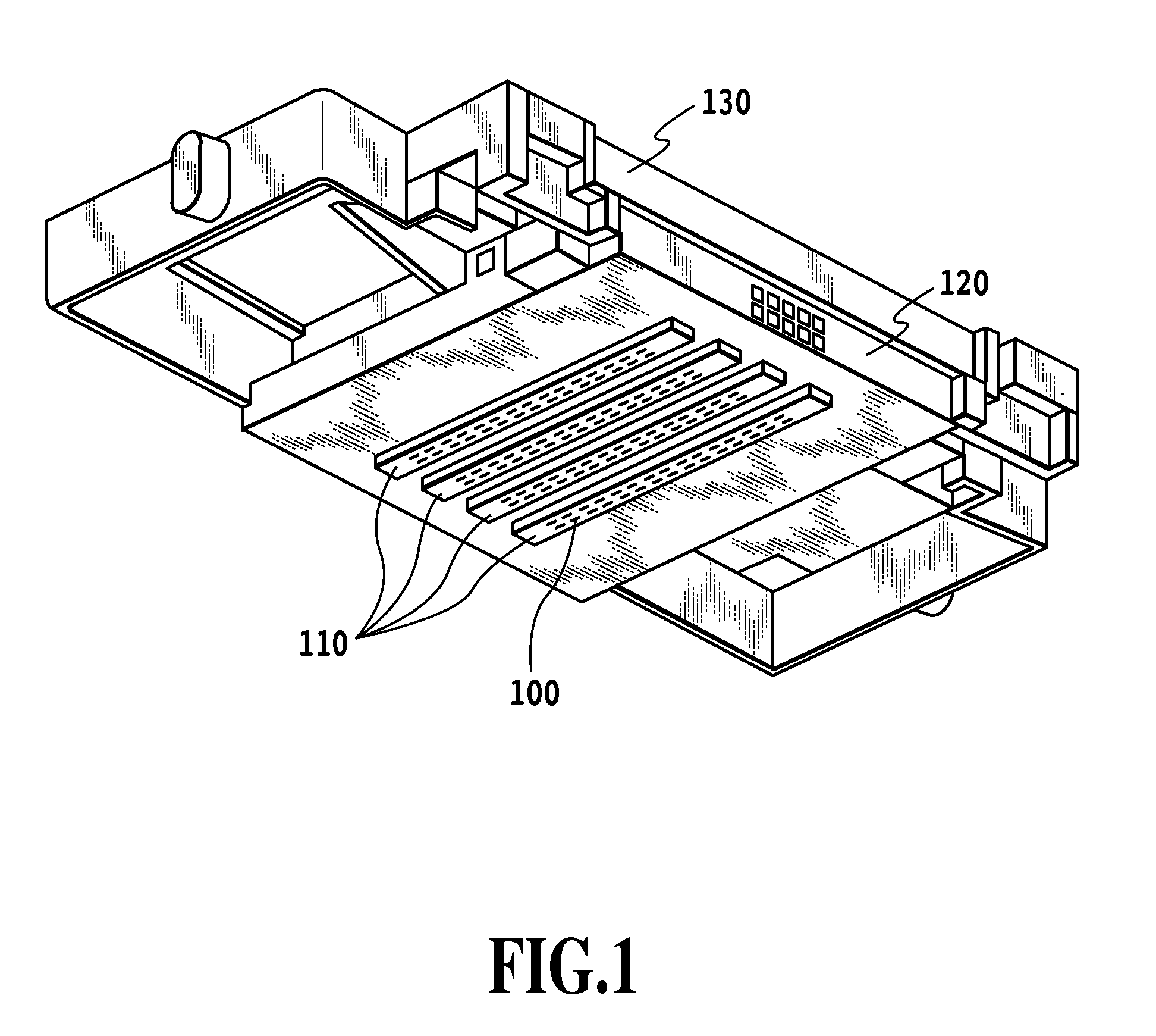
[0037]Now, a first embodiment of this invention will be explained by referring to the accompanying drawings. FIG. 1 is a perspective view showing a print head capable of applying the present invention. The print head of this embodiment includes a support substrate 120, a liquid ejection substrate 110 mounted on the support substrate 120, and a liquid supply member 130. The liquid ejection substrate 110 is formed with a plurality of ejection openings 100 for ejecting liquid. A liquid supplied from the liquid supply member 130 passes through a liquid supply port (not shown) provided in the support substrate 120 to reach the liquid ejection substrate 110. The liquid supplied to the liquid ejection substrate 110 can be ejected from the ejection openings 100 by ejection energy generation devices (electrothermal transducing elements or heaters, not shown) installed in the liquid ejection substrate 110.
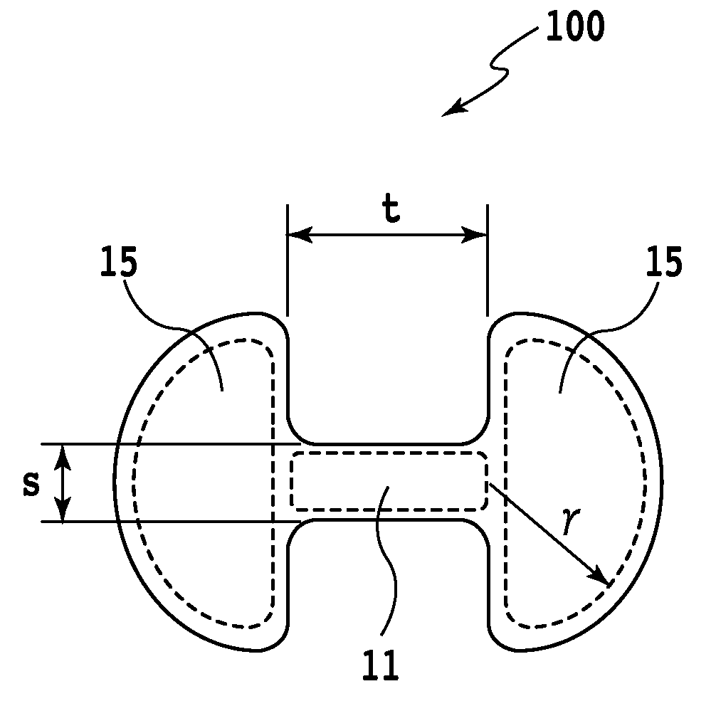
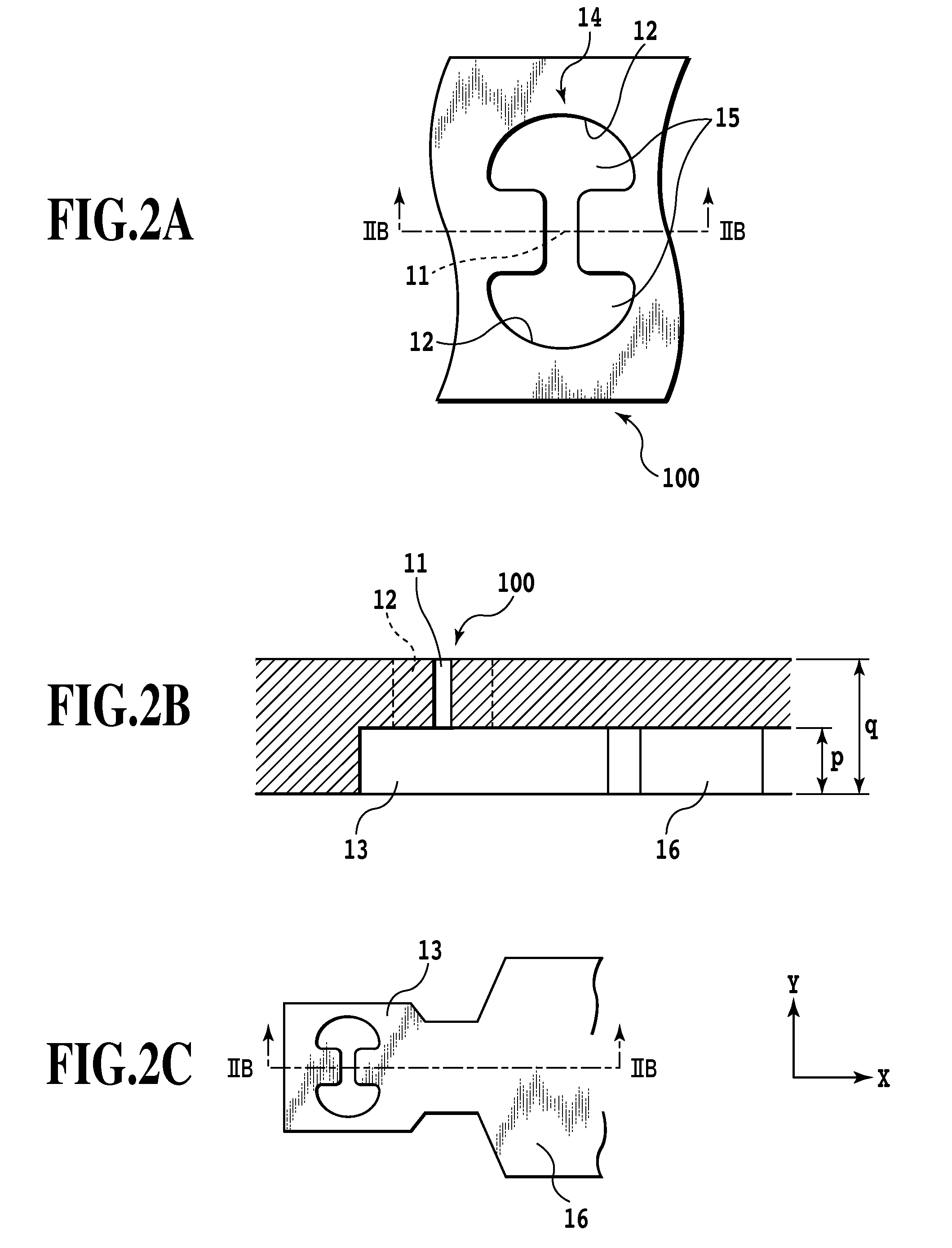
[0038]FIG. 2 illustrates one of the ejection openings 100, which is an essential portion...
second embodiment
[0048]This embodiment is shown to have three openings, as opposed to two employed in the first embodiment. A second embodiment of this invention will be explained by referring to the accompanying drawings.
[0049]FIG. 5 is a front view showing an ejection opening 200 of this embodiment. The ejection opening 200 of this embodiment has two sets of ejection opening 100 of the first embodiment combined. In the example shown, the openings 15 are circular openings 215, and one set of openings is rotated 90 degrees about a central portion of the constricted connection portion 11 and overlapped on the other set. Other constructions are similar to the first embodiment. This arrangement makes it easy for the droplets to easily combine together.
third embodiment
[0050]A third embodiment of this invention will be explained by referring to the accompanying drawings. FIG. 6 is a front view showing another ejection opening 300 according to this embodiment. In FIG. 6 the ejection opening is constructed of three openings 315 and a constricted connection portion 311 that connects the openings at the central portion. This construction can also produce the similar effects to those of the first embodiment. As described above, the number and arrangement of the openings can be determined appropriately and these openings need only to be connected together by the constricted connection portion.
PUM
 Abstract
Description
Claims
Application Information
 - R&D
- Intellectual Property
- Life Sciences
- Materials
- Tech Scout
- Unparalleled Data Quality
- Higher Quality Content
- 60% Fewer Hallucinations
Browse by: Latest US Patents, China's latest patents, Technical Efficacy Thesaurus, Application Domain, Technology Topic, Popular Technical Reports.
© 2025 PatSnap. All rights reserved.Legal|Privacy policy|Modern Slavery Act Transparency Statement|Sitemap|About US| Contact US: help@patsnap.com


