Liquid ejection head and liquid ejection method

a liquid ejection and liquid ejection technology, applied in the direction of printing, inking apparatus, etc., can solve the problems of degrading the print quality, affecting the air resistance more easily, and early disconnection, and achieve the effect of reducing the deviation of the dot landing position

Active Publication Date: 2011-06-28
CANON KK
View PDF2 Cites 9 Cited by
  • Summary
  • Abstract
  • Description
  • Claims
  • Application Information

AI Technical Summary

Benefits of technology

[0011]It is therefore an object of this invention to provide a liquid ejection method that causes small-volume ink droplets to be ejected from ejection openings and to combine together on the fly to become a larger droplet which is not easily affected by air flows, thus realizing a printing operation with little dot landing position deviations.
[0014]With this invention, a liquid droplet to be ejected is divided into a plurality of liquid columns as it passes through the ejection opening, thus making individual column portions of the droplet narrower to advance the timing when the droplet is disconnected from the body of liquid. Between the individual liquid columns is provided a contact portion that causes the liquid column portions to get united quickly after the droplet has parted from the body of the liquid. Thus the liquid, while flying, can be made a large droplet. This makes it possible to provide a liquid ejection method capable of realizing highly precise printing which is hardly susceptible to influences of mist and satellites and influences of air flows and therefore has minimal landing position deviations.

Problems solved by technology

Generally, the ink tail is smaller in volume and slower than the main droplet and thus lands on the print medium at a position deviated from that of the main droplet, degrading the print quality.
This is because a reduced volume of liquid droplet naturally results in an early disconnection.
The smaller volume of droplet, however, has a disadvantage in that it is more easily affected by air resistance and therefore air flows around the print head.
This will result in positional deviations of printed dots on the print medium, degrading the print quality.
The ejection state variations (deflections of ejection direction and variations in ejection volume) may result in a combined ink droplet being deflected from an intended direction and, in a worst case, small ink droplets failing to join together.
So, it is difficult, with the present construction as is, to eject ink droplets in a way that can stably keep their ejected state.
Even if the ejection of independent droplets and the subsequent joining of droplets should be able to be realized under a certain condition, since the two-hole distance is based on the subtle condition, any change in conditions during use, such as an ink property and a surface state of ejection openings, can result in the independent droplets failing to combine or the ink being ejected as a single dot from the beginning, thus degrading the print quality.

Method used


Image

  • Liquid ejection head and liquid ejection method
  • Liquid ejection head and liquid ejection method
  • Liquid ejection head and liquid ejection method

Examples


first embodiment

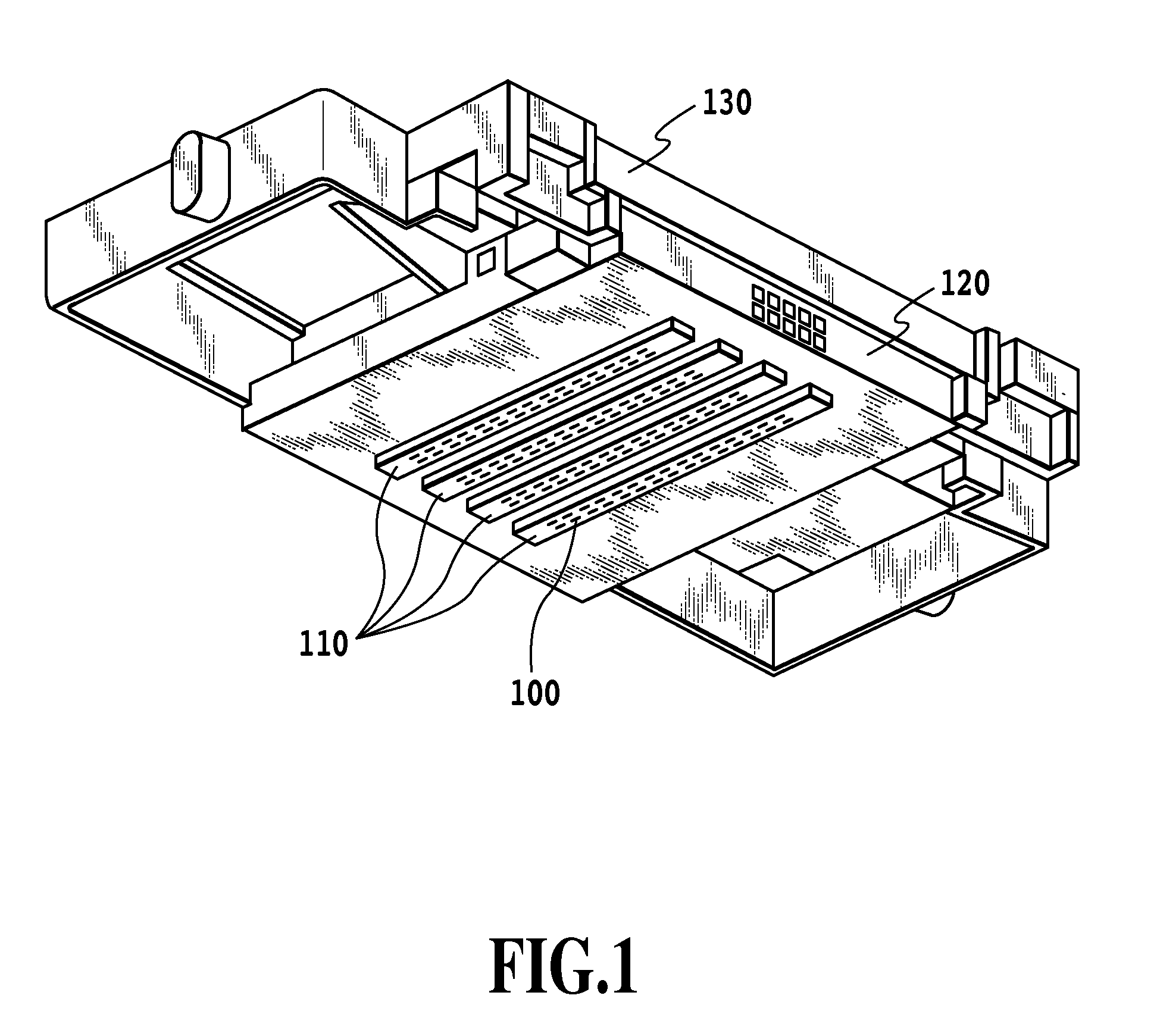
[0037]Now, a first embodiment of this invention will be explained by referring to the accompanying drawings. FIG. 1 is a perspective view showing a print head capable of applying the present invention. The print head of this embodiment includes a support substrate 120, a liquid ejection substrate 110 mounted on the support substrate 120, and a liquid supply member 130. The liquid ejection substrate 110 is formed with a plurality of ejection openings 100 for ejecting liquid. A liquid supplied from the liquid supply member 130 passes through a liquid supply port (not shown) provided in the support substrate 120 to reach the liquid ejection substrate 110. The liquid supplied to the liquid ejection substrate 110 can be ejected from the ejection openings 100 by ejection energy generation devices (electrothermal transducing elements or heaters, not shown) installed in the liquid ejection substrate 110.

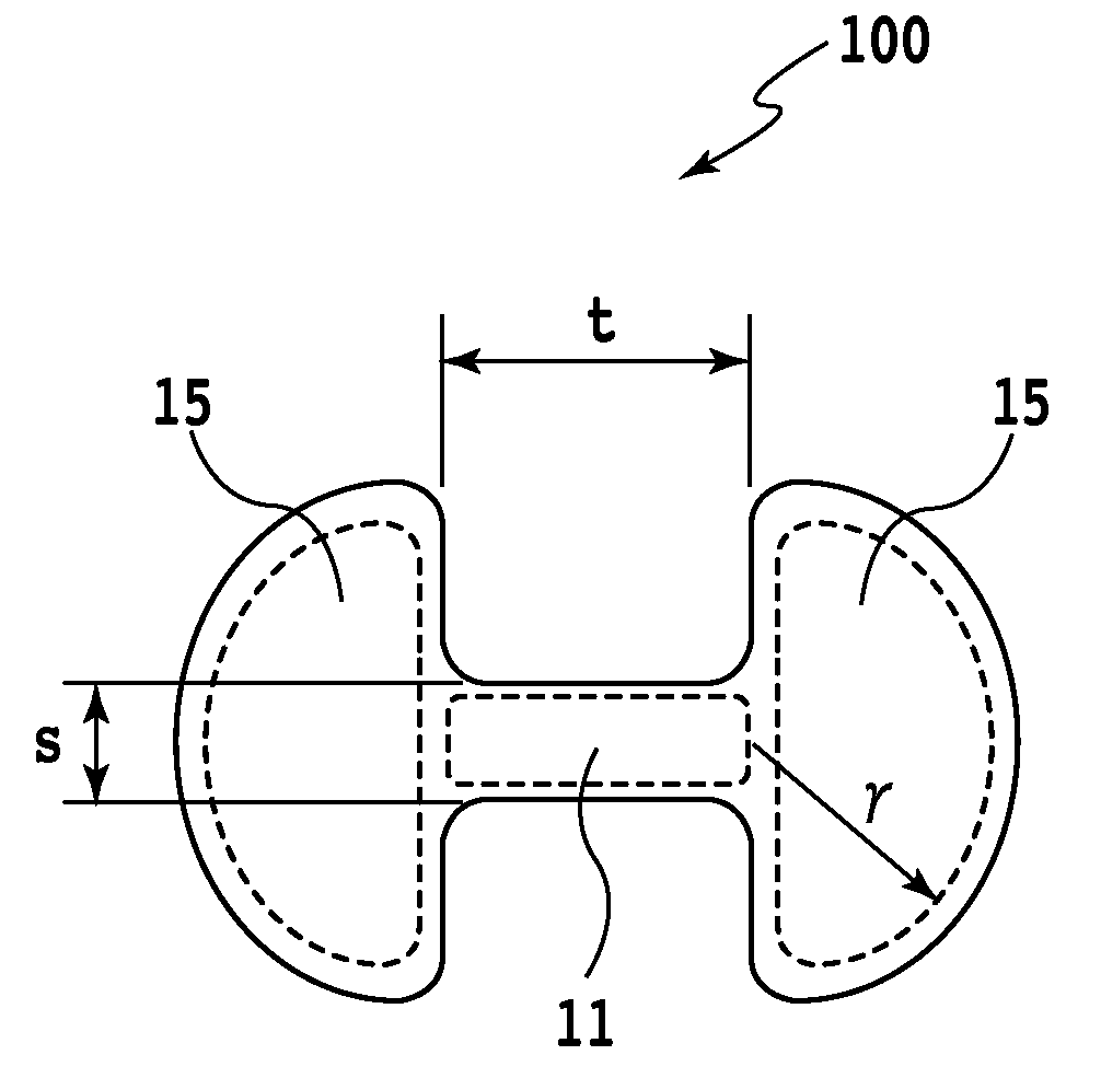
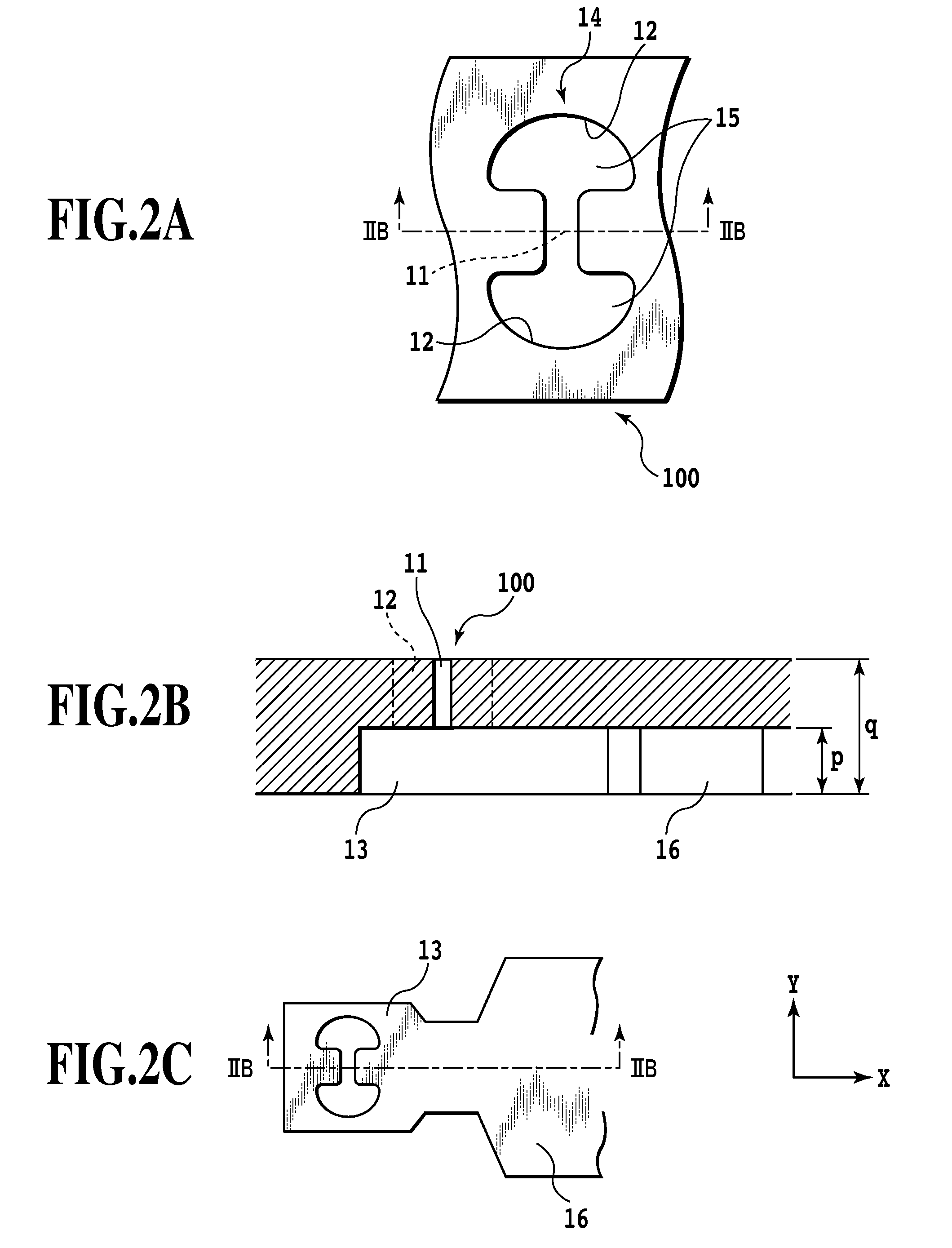
[0038]FIG. 2 illustrates one of the ejection openings 100, which is an essential portion...

second embodiment

[0048]This embodiment is shown to have three openings, as opposed to two employed in the first embodiment. A second embodiment of this invention will be explained by referring to the accompanying drawings.

[0049]FIG. 5 is a front view showing an ejection opening 200 of this embodiment. The ejection opening 200 of this embodiment has two sets of ejection opening 100 of the first embodiment combined. In the example shown, the openings 15 are circular openings 215, and one set of openings is rotated 90 degrees about a central portion of the constricted connection portion 11 and overlapped on the other set. Other constructions are similar to the first embodiment. This arrangement makes it easy for the droplets to easily combine together.

third embodiment

[0050]A third embodiment of this invention will be explained by referring to the accompanying drawings. FIG. 6 is a front view showing another ejection opening 300 according to this embodiment. In FIG. 6 the ejection opening is constructed of three openings 315 and a constricted connection portion 311 that connects the openings at the central portion. This construction can also produce the similar effects to those of the first embodiment. As described above, the number and arrangement of the openings can be determined appropriately and these openings need only to be connected together by the constricted connection portion.


PUM


Abstract

A liquid ejection method is provided which ejects small-volume droplets from ejection openings and causes them to reliably combine together on the fly into a large droplet that is less susceptible to influences of air flows, thus realizing a printing with reduced droplet landing position deviations. To that end, each of the ejection openings is constructed of two openings spaced apart and a slit-like constricted connection portion that connects the two openings together.

Description

BACKGROUND OF THE INVENTION[0001]1. Field of the Invention[0002]The present invention relates to a liquid ejection head and a liquid ejection method of performing printing by ejecting a liquid, and more particularly to a method of joining a plurality of liquid droplets during ejection.[0003]2. Description of the Related Art[0004]A print head, used in ink jet printing and that performs printing by ejecting a liquid onto a print medium, applies energy such as heat to the liquid to cause a status change in the liquid accompanied by a rapid liquid volume change, thereby ejecting the liquid from ejection openings by a status change-produced force.[0005]With this ink jet printing system, high-quality images can be printed at high speed with low noise. Further, the ink jet printing system is able to arrange liquid ejection openings at high density in the print head. The ability of the ink jet printing apparatus to arrange the ejection openings at high density provides many advantages. Amon...

Claims


Application Information

Patent Timeline
Patent Type & Authority Patents(United States)
IPC IPC(8): B41J2/14
CPCB41J2/1404B41J2202/11B41J2002/14475
Inventor KOIZUMI, RYOICHIMURAKAMI, SHUICHITAKEI, YASUNORI
Owner CANON KK
Why Eureka
Try Eureka