Supercharge Your Innovation With Domain-Expert AI Agents!

Plastic semi-permanent retainer ring

a semi-permanent, plastic technology, applied in the direction of fastening means, connections, mechanical equipment, etc., can solve problems such as ring shrinkag

Inactive Publication Date: 2008-11-27
TOYOTA MOTOR ENGINEERING & MANUFACTURING NORTH AMERICA
View PDF40 Cites 2 Cited by
  • Summary
  • Abstract
  • Description
  • Claims
  • Application Information

AI Technical Summary

Benefits of technology

The patent describes a way to secure a shaft within a component by creating a semi-permanent ridge on the shaft. This is done using a ring made from a heat shrinkable polymer that will shrink when heated. The ring is placed on the shaft and then heated, causing the ring to shrink and fit snugly within the radial groove on the shaft. The securement ridge can be easily removed by cutting or prying off the ring. The technical effect of this invention is a simple and effective way to securely attach components together.

Problems solved by technology

Once placed onto the shaft and the radial groove, heating of the ring above the release temperature results in ring shrinkage such that the ring inner diameter and the radial groove inner diameter are in contact with each other.

Method used


Image

  • Plastic semi-permanent retainer ring
  • Plastic semi-permanent retainer ring
  • Plastic semi-permanent retainer ring

Examples


Embodiment Construction

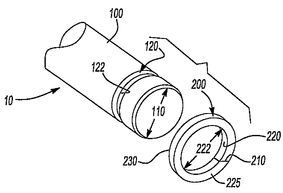
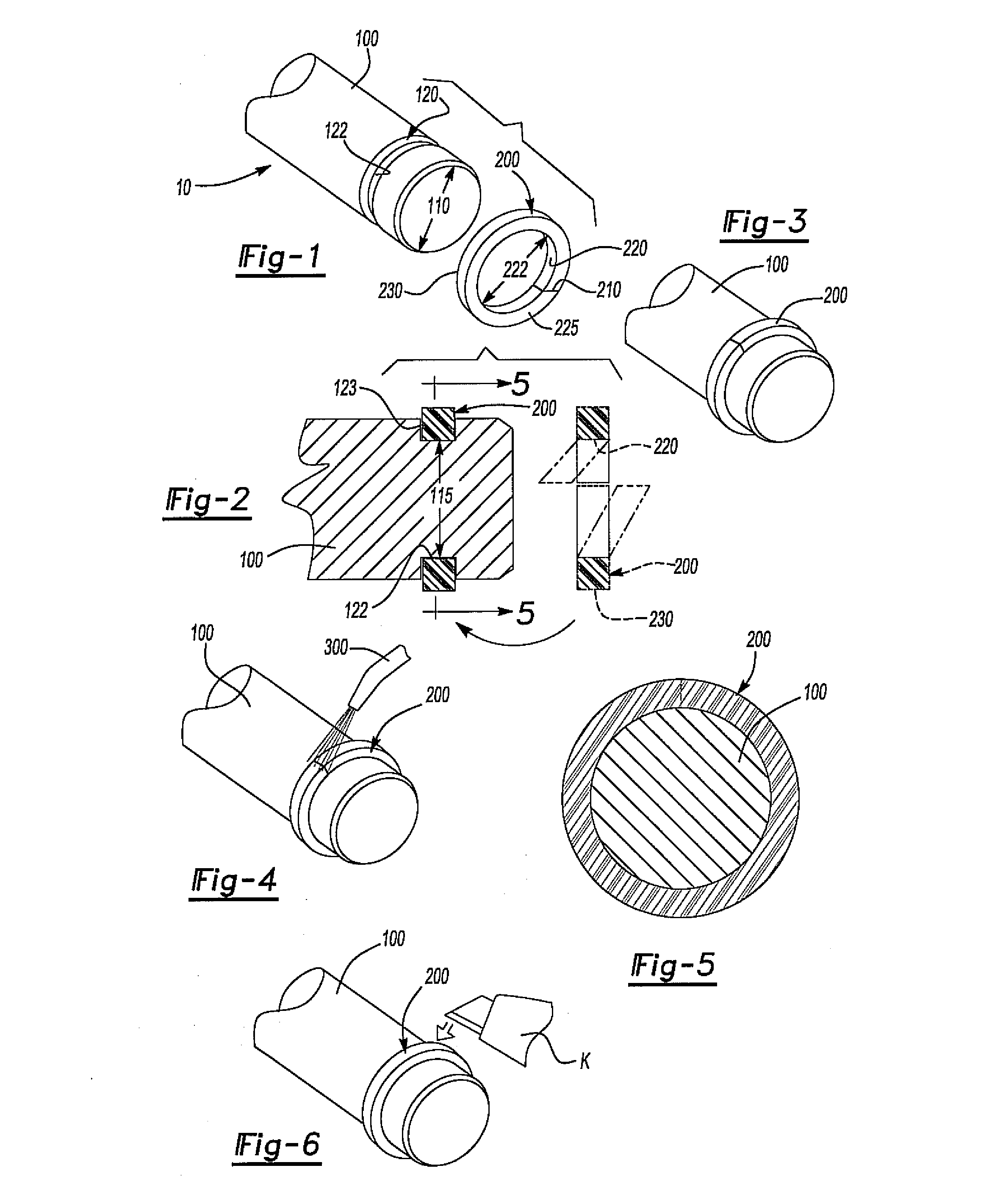
[0020]The present invention discloses a semi-permanent retainer mechanism in the form of a simple to use plastic retainer ring that prevents undesirable lateral movement of a component on a shaft. As such, the present invention has utility as a retainer ring used to prevent unwanted removal and / or movement of components on a shaft.

[0021]The semi-permanent plastic retainer ring of the present invention is made from a heat shrinkable polymer. The ring can include a generally axially oriented split separation which affords for the opening and / or expanding of the ring and subsequent placement onto a shaft. Once placed onto the shaft, the ring can be heated above a release temperature of the heat shrinkable polymer and allowed to shrink onto the shaft. Shrinking of the ring onto the shaft provides a circumferential ridge which can prevent lateral movement of a component on the shaft.

[0022]Referring now to FIGS. 1-3, an embodiment of the present invention is shown wherein a shaft 100 with...


PUM


Abstract

A semi-permanent retainer mechanism for securing a shaft within a component by forming a semi-permanent ridge on the shaft is provided. The mechanism includes a ring made from a heat shrinkable polymer that will heat shrink into a radial groove on the shaft. The heat shrinkable polymer of the ring has a release temperature wherein the ring shrinks in size when heated to a temperature above the release temperature. The ring has a pre-release size that is larger than the radial groove and a release size that is smaller than the outer circumference of the shaft.

Description

FIELD OF THE INVENTION[0001]This invention relates generally to a retainer ring. More specifically, the invention relates to a semi-permanent plastic retainer ring.BACKGROUND OF THE INVENTION[0002]Fastener and / or retainer mechanisms are used in a variety of applications and industries in order to prevent undesired movement of a component. If the component is located on a shaft, bar, rod and the like, undesired lateral movement of the component can result in significant damage to surrounding articles, structures and the like.[0003]One type of fastener that can be used on a shaft is a circlip, also known as a snap ring, which consists of a semi-flexible metal ring with open ends which can be snapped into place within a machined groove of the shaft. The snap ring allows rotation of a part on the shaft but prevents lateral movement. Although useful, the snap ring requires a metal stamping operation which increases the cost of the component. In addition, failure of the snap ring during s...

Claims


Application Information

Patent Timeline
Patent Type & Authority Applications(United States)
IPC IPC(8): F16B4/00
CPCY10T403/48F16B4/006
Inventor GILLEY, MARK
Owner TOYOTA MOTOR ENGINEERING & MANUFACTURING NORTH AMERICA
Features
  • R&D
  • Intellectual Property
  • Life Sciences
  • Materials
  • Tech Scout
  • Unparalleled Data Quality
  • Higher Quality Content
  • 60% Fewer Hallucinations
Learn More