Magnetic latch for a voice coil actuator

a voice coil actuator and magnetic latch technology, which is applied in the direction of electromagnetic relays, emergency protective arrangements for automatic disconnection, magnets, etc., can solve the problems of needlessly complex, needless energy to release the latch, and the voice coil has no inherent stable position when it is not powered, etc., to achieve the effect of simple and energy-efficient methods

Inactive Publication Date: 2008-12-04
COOPER TECH CO
View PDF17 Cites 1 Cited by
  • Summary
  • Abstract
  • Description
  • Claims
  • Application Information

AI Technical Summary

Benefits of technology

[0011]The invention provides a simple and energy-efficient method and device for latching and releasing a voice coil actuator. Specifically, the invention provides a method and device for magnetically latc

Problems solved by technology

The major disadvantage of a voice coil actuator is that the voice coil has no inherent stable position when it is not powered.
These mechanical mea

Method used


Image

  • Magnetic latch for a voice coil actuator
  • Magnetic latch for a voice coil actuator
  • Magnetic latch for a voice coil actuator

Examples


Embodiment Construction

[0030]The following description of exemplary embodiments refers to the attached drawings, in which like numerals indicate like elements throughout the several figures.

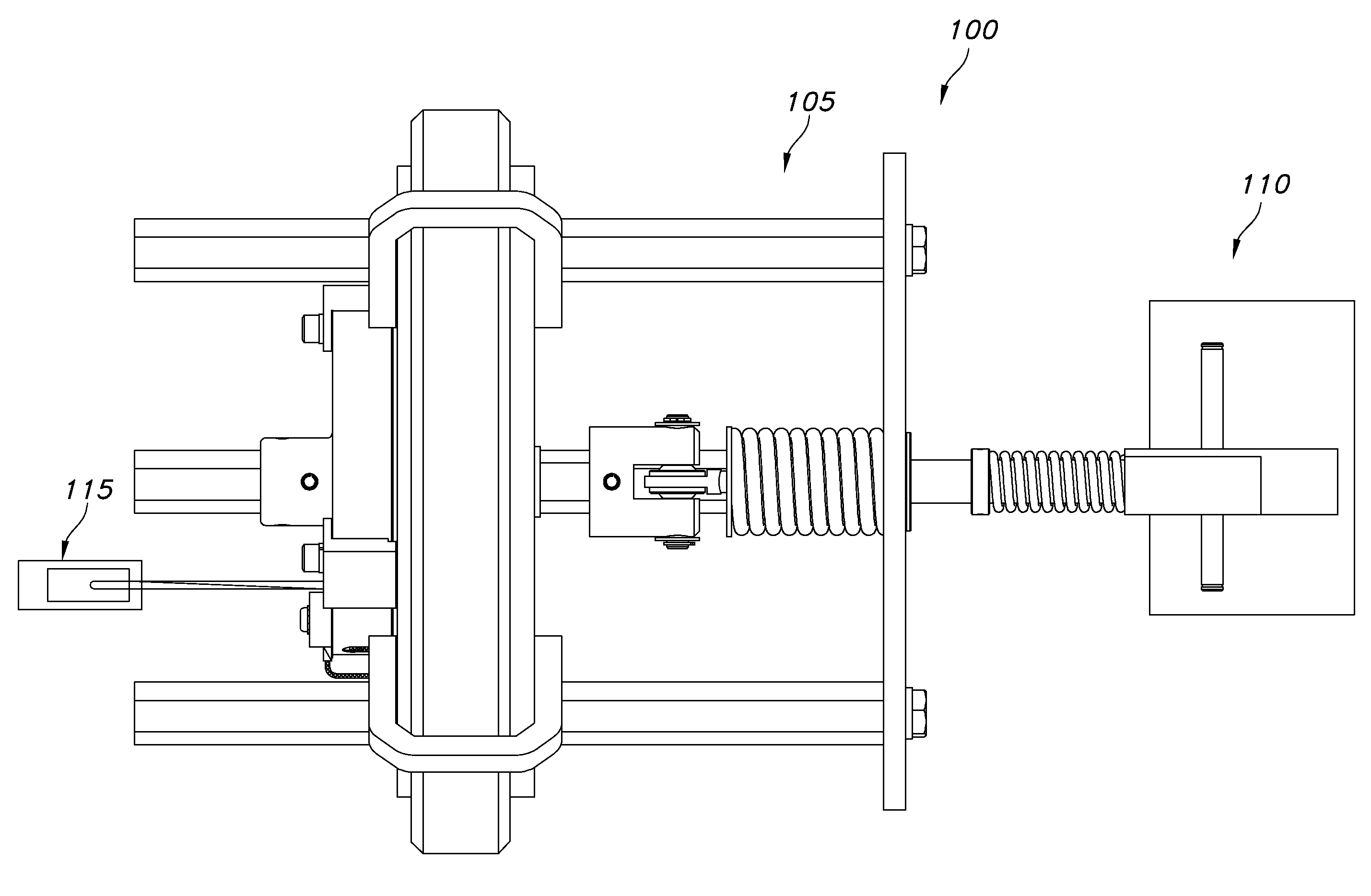
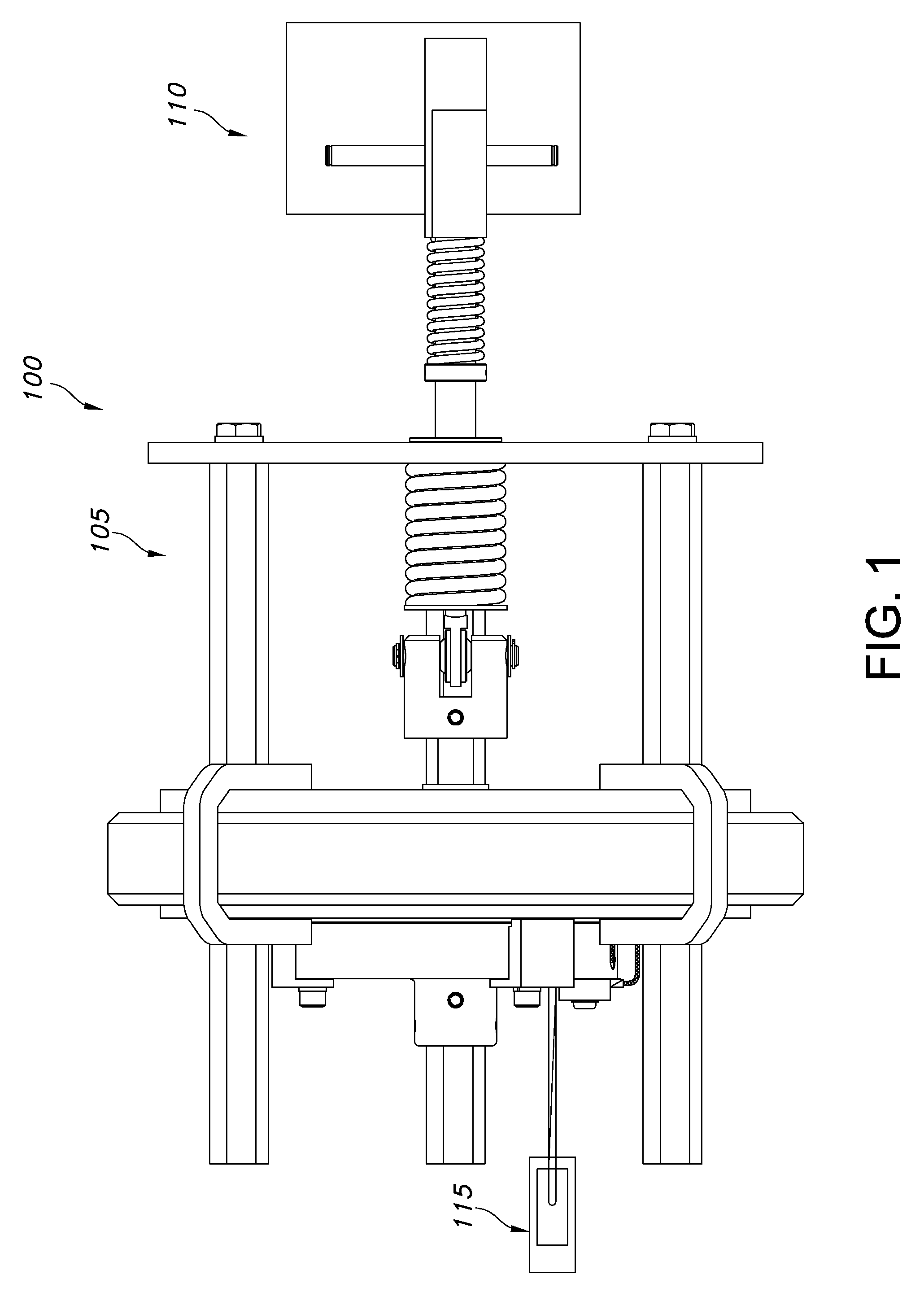
[0031]FIG. 1 is a cross-sectional side view of a switchgear 100 in a closed position, in accordance with certain exemplary embodiments. The switchgear 100 includes a voice coil actuator 105 configured to open and close electrical contacts (771 and 772 in FIG. 7) of a current interrupter 110. A motion circuit 115 of the switchgear is configured to supply power to the voice coil actuator 105, as described below. For example, the switchgear 100 can be a fault interrupter, a recloser, a breaker, or a capacitor switch. The current interrupter 110 is described in more detail below, with reference to FIG. 7.

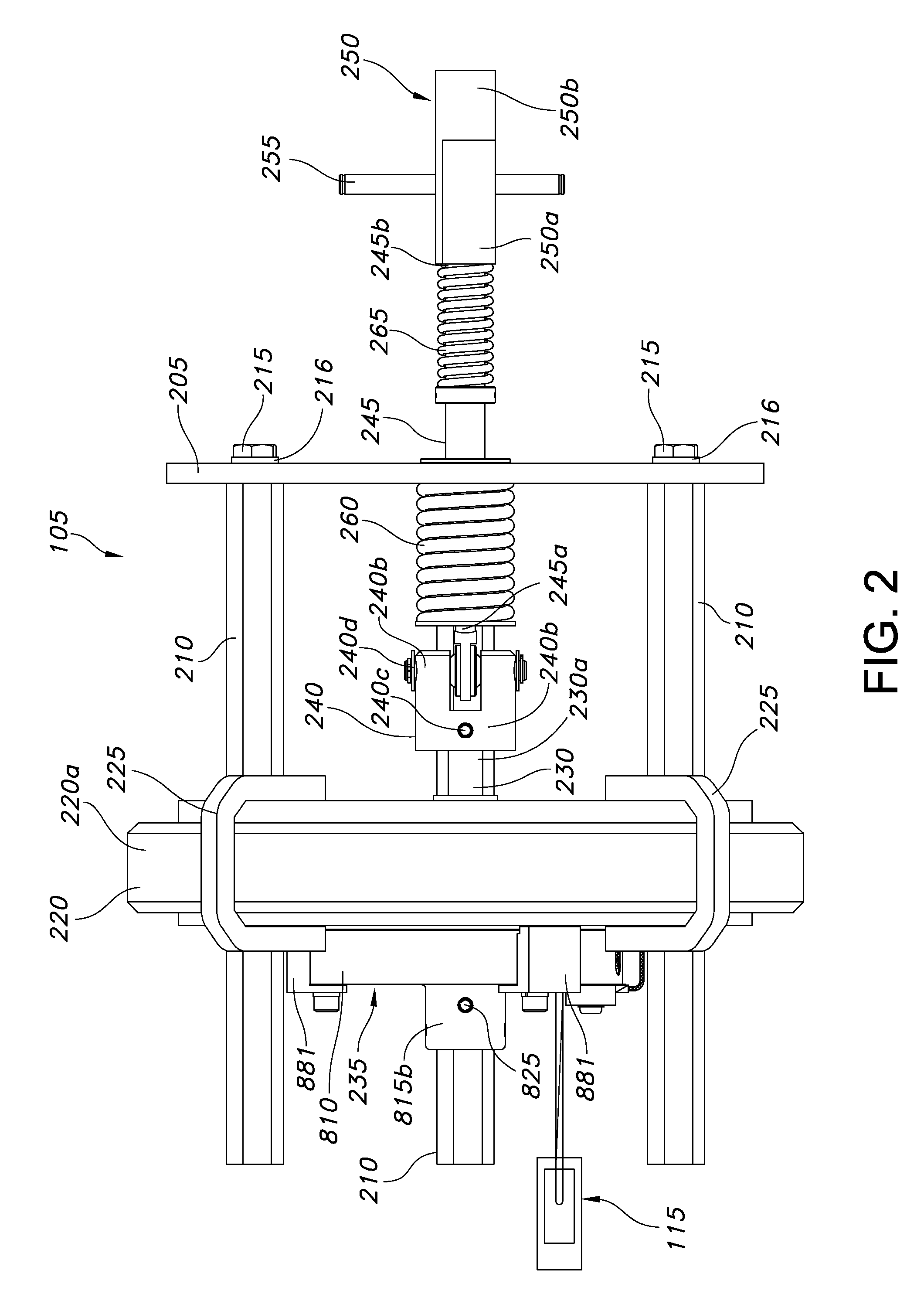
[0032]FIGS. 2-6 are cross-sectional side views of the voice coil actuator 105. FIGS. 2-5 illustrate the voice coil actuator 105 in a closed position. FIG. 6 illustrates the voice coil actuator 105 in an open position.

[0033...


PUM


Abstract

Magnetically latching and releasing a voice coil actuator for controlling electrical switchgear. The voice coil actuator includes a voice coil magnet disposed on a common longitudinal axis with respect to a voice coil assembly. A coil of the voice coil assembly exerts a magnetic force on the voice coil assembly, thrusting the voice coil assembly towards the voice coil magnet. At least one pair of latching members mounted to the voice coil assembly creates a permanent magnet circuit between the latching members and the voice coil magnet. The permanent magnet circuit maintains the position of the voice coil assembly relative to the voice coil magnet, even when power to the coil is removed. This latch can be released by applying a current in the coil or by applying an external, physical force to a member coupled to the voice coil assembly.

Description

TECHNICAL FIELD[0001]The invention relates generally to a method and device for controlling electrical switchgear. More specifically, the invention relates to a method and device for magnetically latching and releasing a voice coil actuator for controlling electrical switchgear.BACKGROUND OF THE INVENTION[0002]In a power distribution system, electrical switchgear are typically employed to protect the system against abnormal conditions, such as power line fault conditions or irregular loading conditions. There are different types of switchgear for different applications. A first type of switchgear is a fault interrupter. Fault interrupters are configured to automatically open a power line upon the detection of a fault condition.[0003]A second type of switchgear is a recloser. Reclosers are configured to respond to a fault condition by rapidly tripping open and then reclosing a power line a number of times, in accordance with a set of time-current curves. After a predetermined number ...

Claims


Application Information

Patent Timeline
IPC IPC(8): H02B11/02
CPCH01H33/6662H01H51/01H01H51/2209
Inventor SZEIFERT, BELA PETERDUNK, MICHAEL PETER
Owner COOPER TECH CO
Why Eureka
Try Eureka