Clock generator including a ring oscillator with precise frequency control

a clock generator and frequency control technology, applied in the direction of pulse generator, pulse technique, digital transmission, etc., can solve the problems of difficult precise control and somewhat inaccurate output of ring oscillator

Inactive Publication Date: 2008-12-04
INTERNATIONAL RECTIFIER COEP
View PDF3 Cites 34 Cited by
  • Summary
  • Abstract
  • Description
  • Claims
  • Application Information

AI Technical Summary

Problems solved by technology

However, the output of ring oscillator tends to be somewhat inaccurate and difficult to precisely control.
Naturally, such features are undesirable in generating a clock signal

Method used


Image

  • Clock generator including a ring oscillator with precise frequency control
  • Clock generator including a ring oscillator with precise frequency control
  • Clock generator including a ring oscillator with precise frequency control

Examples


Embodiment Construction

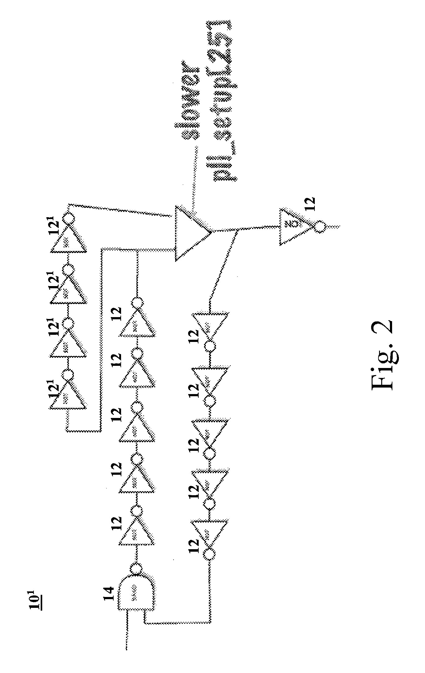
[0020]FIG. 2 illustrates an example of a modified ring oscillator 101 that may work in two modes, a fast mode and a slow mode. The frequency of the oscillator 101 is faster in the fast mode than in the slow mode. In this case, additional inverters 121 may be selectively added to the series to slow down the frequency of the oscillator. The slower mode is triggered by a control signal (slower pll_setup) that is preferably provided by a phase lock loop (PLL) (not shown). The use of a phase lock loop in clock and / or oscillator control is well known, and thus, will not be discussed in detail herein.

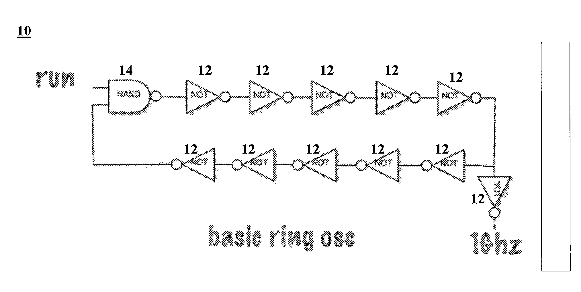
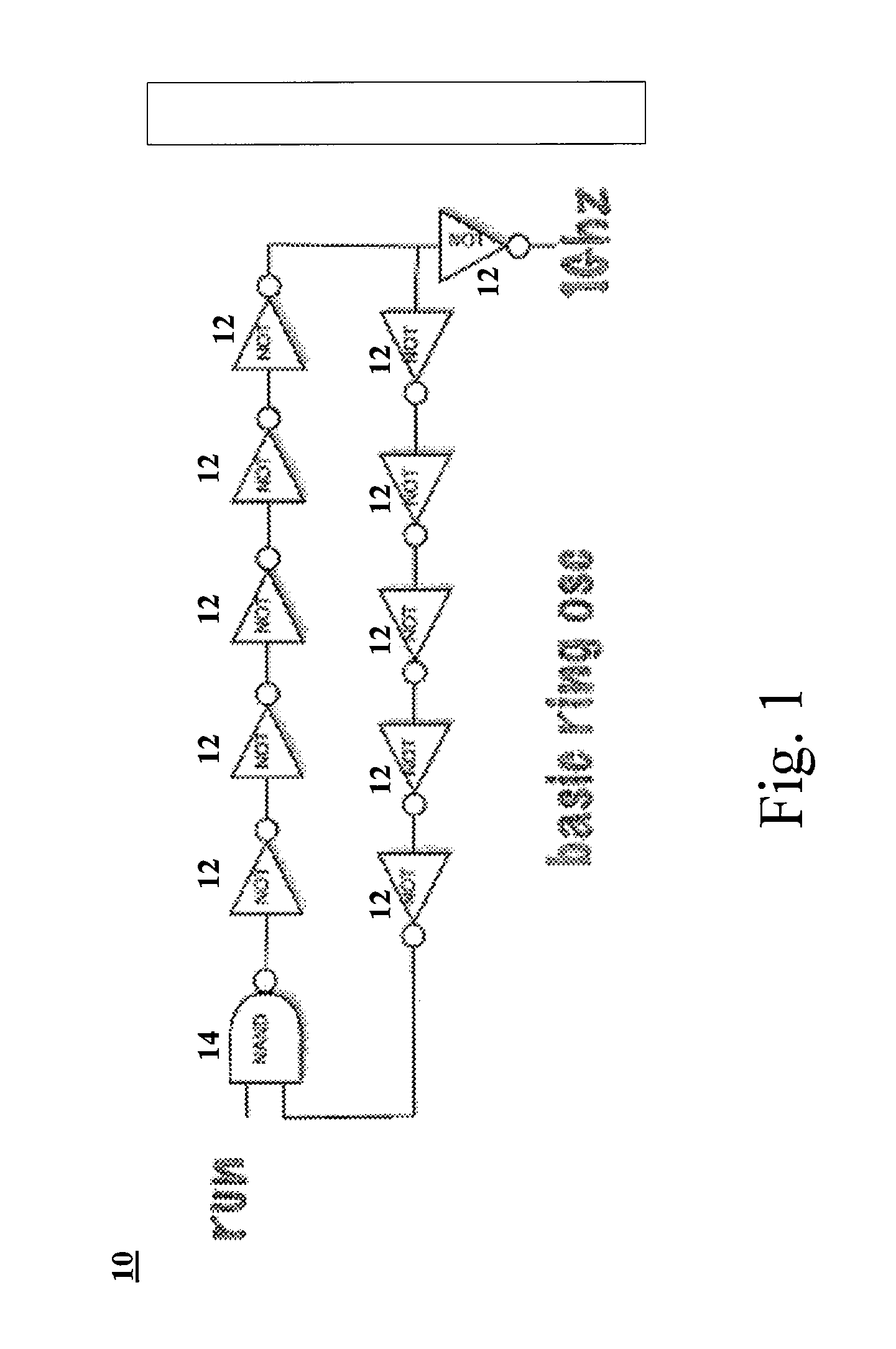
[0021]FIG. 3 illustrates a schematic diagram of a clock generator 100 that utilizes a ring oscillator 10 to provide a desired clock signal (elk) in accordance with an embodiment of the present application. In FIG. 3, the output of the ring oscillator 10 is preferably a 1 Ghz signal, similar to that provided by the ring oscillator 10 of FIG. 1. This signal is divided by the divider 40 to reduce...


PUM


Abstract

A clock generator for providing a desired system clock signal in accordance with an embodiment of the present application includes a ring oscillator operable to provide an oscillator output signal having a first frequency, a divider operable to divide the oscillator output signal by a predetermined divisor and to output the divided signal as the desired system clock signal, a reference device operable to provide a reference signal with a known second frequency and a ratio device operable to provide a ratio value indicative of a relationship between the oscillator output signal and the reference signal, wherein the predetermined divisor of the divider is determined based on the ratio value such that the desired system clock signal has a desired frequency.

Description

CROSS REFERENCE TO RELATED APPLICATION[0001]The present application claims benefit of and priority to U.S. Provisional Patent Application No. 60 / 870,161 entitled DIGITAL TUNABLE CLOCK SCHEME FOR MICROCONTROLLER filed Dec. 15, 2006, the entire contents of which are hereby incorporated by reference herein.BACKGROUND OF THE INVENTION[0002]1. Field[0003]The present invention relates to an improved clock generator. In particular, the present application relates a clock generator utilizing a ring oscillator with precise frequency control.[0004]2. Related Art[0005]A ring oscillator is generally formed by an odd number of NOT gates, or inverters, connected together in series. The output of the last inverter is connected to the first inverter to form a ring. Since an odd number of inverters are used, the output of the last inverter will be the opposite of the value input to the fist inverter. Since this output is then provided to the first inverter, the output of the last inverter will then ...

Claims


Application Information

Patent Timeline
Patent Type & Authority Applications(United States)
IPC IPC(8): H04L7/00
CPCH03K3/0315
Inventor GREENBLAT, ILIAHELZER, AMIR
Owner INTERNATIONAL RECTIFIER COEP
Why Eureka
Try Eureka