Grinding Wheel

a technology of grinding wheel and grinding plate, which is applied in the direction of gear teeth, manufacturing tools, manufacturing apparatus for gear teeth, etc., can solve the problems of high cost of grinding machine, increased time required for grinding, and inability to achieve superhigh-precision surface roughness on the roll surface, etc., and achieves the effect of simple structur

Inactive Publication Date: 2008-12-04
TOYODA VAN MOPPES +1
View PDF2 Cites 12 Cited by
  • Summary
  • Abstract
  • Description
  • Claims
  • Application Information

AI Technical Summary

Benefits of technology

[0012]Further, a present invention is that in the improved grinding wheel according to the first invention, each of the abrasive tips comprises the abrasive layer formed by bonding abrasive grains and a lower layer overlaid and integrally formed with the abrasive layer. Each of the abrasive tips may be attached to the periphery of the base at the lower layer. A Young's modulus of the lower layer of the abrasive tip for finish grinding is less than that of the abrasive tip for rough grinding.
[0013]Thus, as the Young's modulus of the lower layer of the abrasive tip for finish grinding is less than that of the abrasive tips for rough grinding, the amount by which the grinding surface of each abrasive tip is displaced in the loading direction with respect to the load acting on the grinding surface of each abrasive tip in an inward direction of the grinding wheel at the abrasive tips for finish grinding is greater than that at the abrasive tips for rough grinding. This can provide a grinding wheel with simple structure, which is capable of realizing the same effects as the foregoing effects of the invention described in the claim 1.
[0014]Further, a present invention is that in the improved grinding wheel according to any one of the inventions described claim 1 through 3, the abrasive tips for finish grinding and the abrasive tips for rough grinding which are adjacent to each other are bonded by an adhesive having elasticity so that each abrasive tip is capable of independently undergoing elastic deformation in the loading direction.
[0015]Thus, the abrasive tips for rough and finish grinding are bonded with each other by the adhesive having elasticity, so that they can be prevented from being separated from the disk type base. During the truing and rough-grinding, the abrasive tips for finish grinding can be elastically deformed without being restricted by the abrasive tips for rough grinding, and effectively move in an inward direction of the grinding wheel farther than the abrasive tips for rough grinding.
[0016]Further, a present invention is that in the improved grinding wheel according to any one of the inventions described claim 1 through 4, abrasive grains of at least one of the abrasive layer of the abrasive tip for rough grinding and the abrasive layer of the abrasive tip for finish grinding includes superabrasive grains
[0017]Thus, as the abrasive grains of at least one of the abrasive layer of the abrasive tip for rough grinding and the abrasive layer of the abrasive tip for finish grinding are superabrasive grains, the workpiece can be efficiently ground in the state in which the abrasion of the abrasive grains is low.

Problems solved by technology

However, in the above-mentioned conventional grinding machine, as the workpiece is rough-ground by the grinding wheel for rough grinding, and thereafter finish-ground or lapped by the grinding wheel for finish grinding or by the lapping tape, it takes time to move the workpiece from a position opposite the grinding wheel for rough grinding to a position opposite the grinding wheel for finish grinding or a position opposite the lapping tape, so that the time required to perform grinding increases.
Further, there is a problem that the grinding machine is expensive.
Hence, a roll surface cannot be ground with superhigh-precision surface roughness.

Method used


Image

  • Grinding Wheel
  • Grinding Wheel
  • Grinding Wheel

Examples


first embodiment

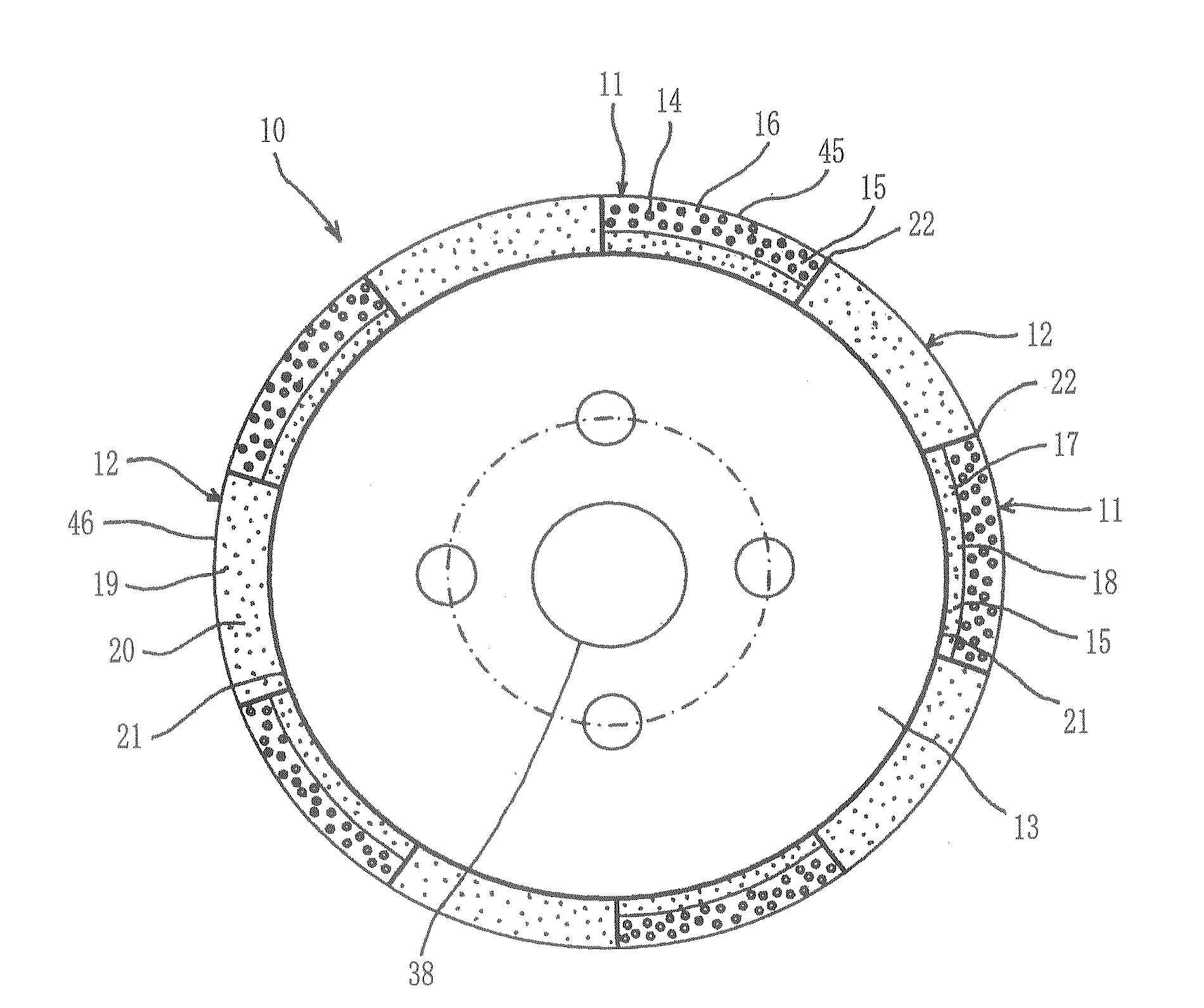
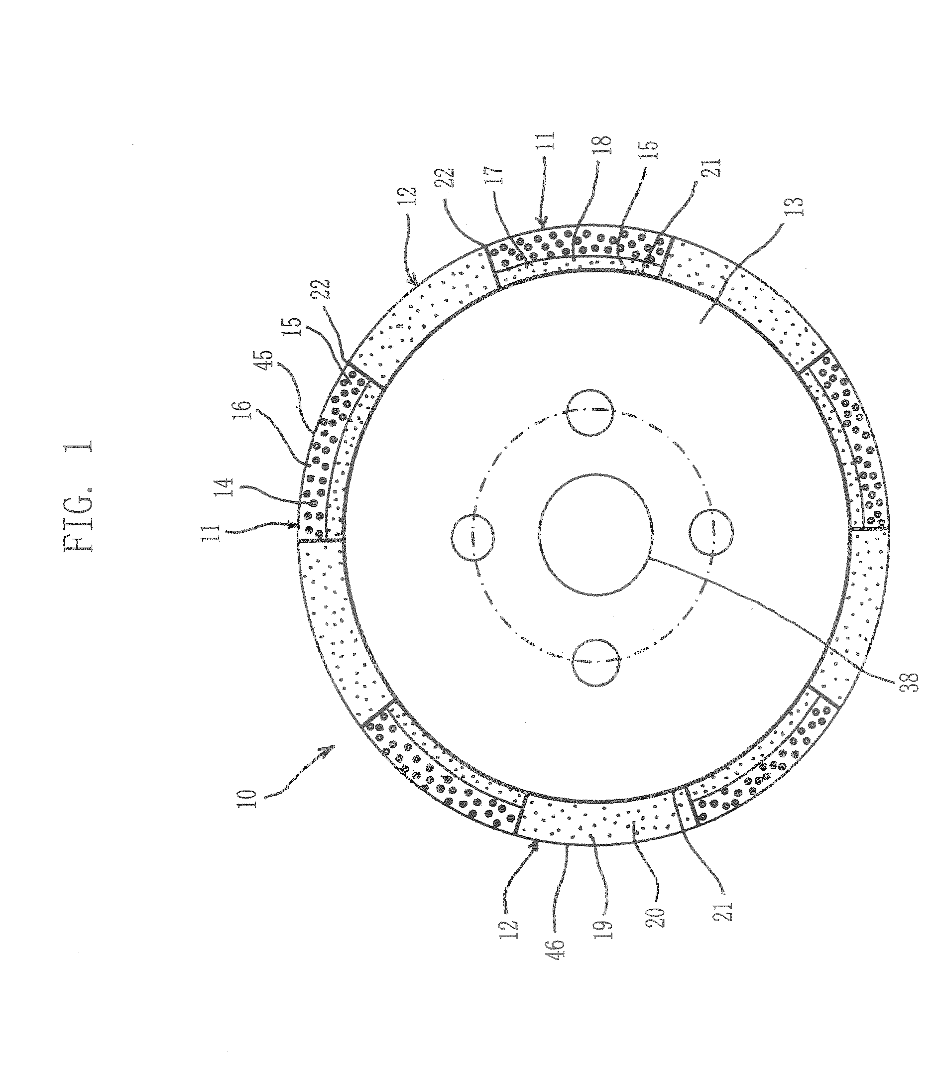
[0030]Hereinafter, the present invention will be described with reference to the drawings. The grinding wheel 10 shown in FIG. 1 includes five abrasive tips 11 for rough grinding and five abrasive tips 12 for finish grinding, in which the abrasive tips for rough grind and finish grinding have different properties each other. The abrasive tips 11 and 12 for rough and finish grinding are alternately bonded on a periphery of a disk type base 13 that rotates around a rotating axis and is formed of metal, such as iron or aluminum, or resin. Each abrasive tip 11 for rough grinding has an arcuate shape, and is integrally formed in such a manner that a abrasive layer 16 formed by bonding superabrasive grains 14 such as cubic boron nitride (CBN), diamond, etc with a binder 15, is formed on a periphery thereof, and a lower layer 17 containing no superabrasive grains is overlaid with the abrasive layer 16 inside the abrasive layer 16. The abrasive layer 16 has an example in which CBN abrasive ...

second embodiment

[0045]In the second embodiment, as illustrated in FIG. 4, on the peripheral surface of a disk type metal base 50, which is made of metal such as aluminum and is rotated about a rotation axis, 15 grooves are formed at an inclination angle of 45 degrees relative to the rotation axis at a predetermined interval, so that there are alternately provided fifteen land and recess regions 51 and 52. In each land region 51, CBN abrasive grains, as superabrasive grains 53 having, for example, a grain size of #60, are electrodeposited on a metal plating layer 54, to form an abrasive section 55 for rough grinding. The superabrasive grains 53 of CBN, diamond, etc. are electrodeposited on the surface of each land region 51 of the disk type metal base 50 by means of an electrolytic process, in which a metal layer of nickel chrome, etc. is formed by electroplating, or a non-electrolytic process, in which a metal layer is formed by electroless plating (chemical plating). in each recess region 52, supe...


PUM


Abstract

In a grinding wheel in which abrasive tips for rough grinding and abrasive tips for finish grinding are alternately bonded to a periphery of a disk type base rotating about a rotation axis, each abrasive tip includes the abrasive layer for ed by bonding abrasive grains and a lower layer overlaid and integrally for led with the abrasive layer. The abrasive tip is attached to the periphery of the base at the lower layer. A Young's modulus of the lower layer of the abrasive tip for finish grinding relative to a load acting on the grinding surface of the abrasive tip in an inward direction of the grinding wheel is less than that of the abrasive tip for rough grinding. Thereby, the surface of a workpiece can be both rough-ground and finish-ground with superhigh-precision surface roughness with using one grinding wheel

Description

TECHNOLOGICAL FIELD[0001]The present invention relates to a grinding wheel in which abrasive layers respectively having different properties suitable for rough grinding and finish grinding a workpiece, are alternately formed on the periphery of a disk type base.BACKGROUND ART[0002]In order to grind the surface of a workpiece with high-precision surface roughness a grinding machine is provided with two grinding wheel heads, on one of which a grinding wheel for rough grinding is rotatably supported, and on the other of which a grinding wheel for finish grinding is rotatably supported. The grinding machine rough-grinds the workpiece with high grinding efficiency with using the grinding wheel for rough grinding and then finish-grinds the rough-ground workpiece with high-precision surface roughness with using the grinding wheel for finish grinding. It is done that after the rough grinding with using the grinding wheel, the workpiece is lapped for high-precision surface roughness with usi...

Claims


Application Information

Patent Timeline
Patent Type & Authority Applications(United States)
IPC IPC(8): B24B23/02
CPCB24D5/14
Inventor MOROTO, TAKAYUKIUNNO, KUNIHIKOKITAJIMA, MASATOIMAI, TOMOYASUSEKIYA, YASUHISAINAGAKI, TOMOHIROHIRAWA, NOBORUTAKEHARA, HIROSHISAKURAI, TOSHIAKISOMA, SHINJI
Owner TOYODA VAN MOPPES
Why Eureka
Try Eureka