Quick-detachable terminal block assembly

Inactive Publication Date: 2008-12-18
DINKLE ENTERPRISE
View PDF10 Cites 19 Cited by
  • Summary
  • Abstract
  • Description
  • Claims
  • Application Information

AI Technical Summary

Benefits of technology

[0008]The present invention has been accomplished under the circumstances in view. It is the main object of the present invention to provide a quick-detachable terminal block assembly, which can easily and quickly be installed in a circuit board and locked thereto and, which can easi

Problems solved by technology

This mounting procedure is complicated, wasting much time.
Further much operation space is needed for the operation of the tool to fasten the screws or rivets.
Further, when screws are used, the screws may fall out of place upon vibr

Method used


Image

  • Quick-detachable terminal block assembly
  • Quick-detachable terminal block assembly
  • Quick-detachable terminal block assembly

Examples


Embodiment Construction

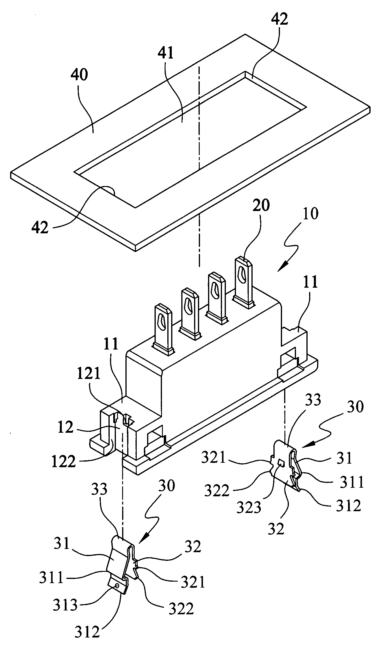
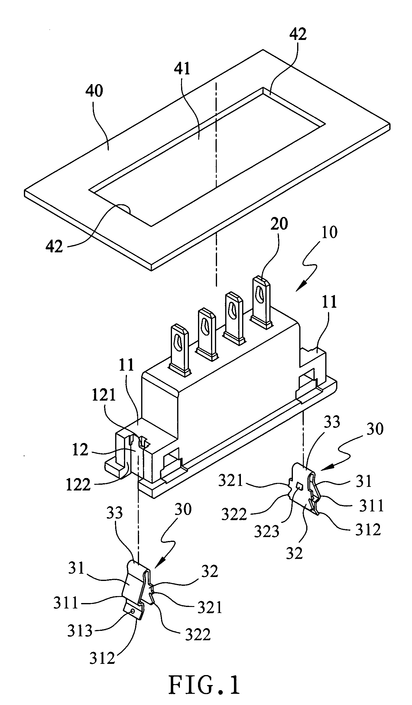
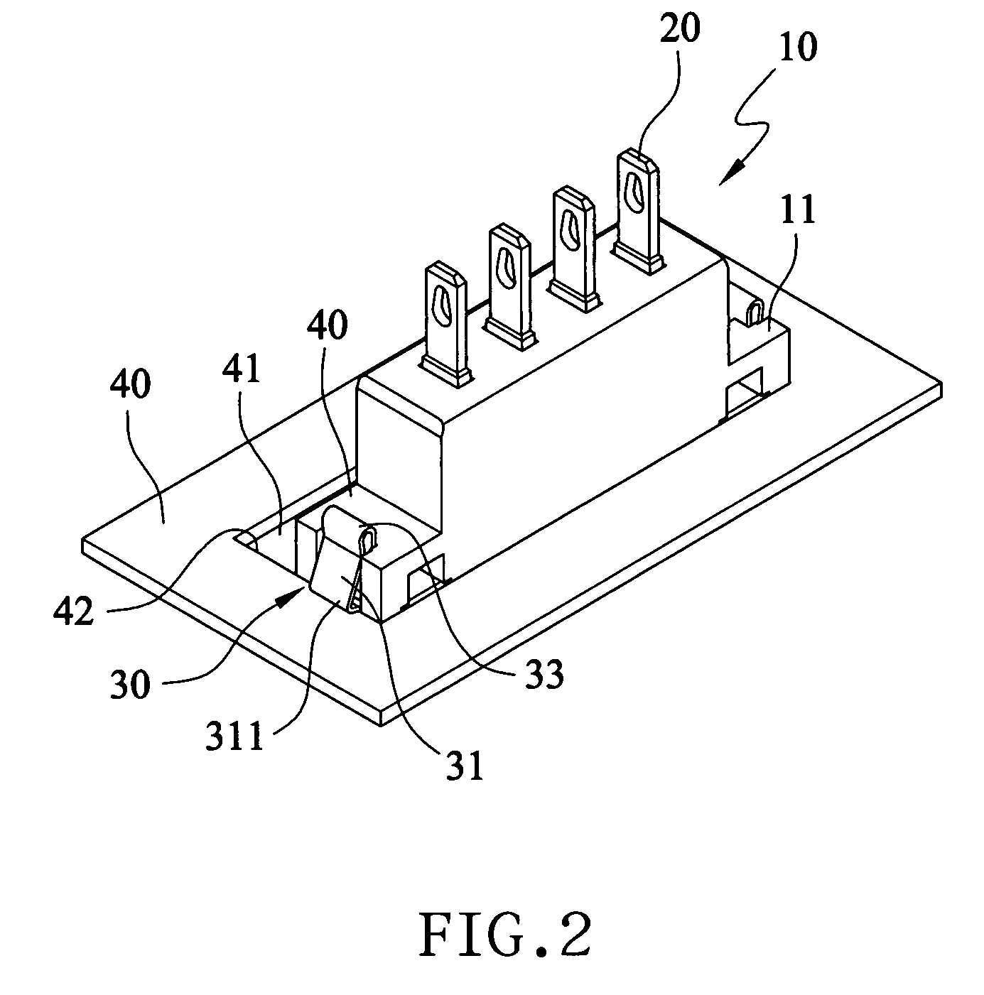
[0019]Referring to FIGS. 1, 2, and 5, a quick-detachable terminal block assembly in accordance with the present invention is shown comprising a terminal block 10 and a plurality of metal terminals 20 mounted in the terminal block 10 and partially extending out of the top wall of the terminal block 10. The terminal block 10 has two mounting blocks 12 at two sides, and a locating groove 12 at each of the two mounting blocks and a retaining hole 121 in each locating groove 12. A metal spring leaf 30 is mounted in each locating groove 12 and stopped between two opposite sidewalls 122 of the associating locating groove 12.

[0020]Referring to FIG. 7 and FIGS. 1 and 5 again, the metal spring leaf 30 has a V-shaped profile invertedly mounted in the associating locating groove 12, i.e., the metal spring leaf 30 has a U-turn 33 on the middle, a front clamping panel 31 extending from one end of the U-turn 33, and a rear mounting panel 32 extending from the other end of the U-turn 33. The rear m...


PUM


Abstract

Disclosed is a quick-detachable terminal block assembly, which includes a terminal block detachably mounted in a mounting through hole of a circuit board, a plurality of conducting terminals mounted in the terminal block and extending out of the top side of the terminal block, and two metal spring leaves each having rear mounting panel affixed to a respective locating groove at each of two opposite sides of the terminal block and a front clamping panel for locking the terminal block to the circuit board after insertion of the terminal block through the mounting through hole. The front clamping panel has a release tip for pressing by the user to disengage the terminal block from the circuit board.

Description

BACKGROUND OF THE INVENTION[0001]1. Field of the Invention[0002]The present invention relates generally to terminal blocks and more particularly, to a quick-detachable terminal block assembly, which has two metal spring leaves provided at two sides for locking the terminal block to a circuit board after insertion of the terminal block through a mounting through hole on the circuit board.[0003]2. Description of the Related Art[0004]A terminal block is a small block holding a number of conducting terminals at one side of a circuit board for the bonding of an electric connector or other circuit means.[0005]A conventional terminal block has an upwardly protruding middle part, and mounting holes on the two opposite mounting blocks at two sides of the upwardly protruding middle part. The conducting terminals extend out of the top side of the upwardly protruding middle part. During installation, mounting screws or rivets are mounted in the mounting holes of the terminal block and fastened ...

Claims


Application Information

Patent Timeline
IPC IPC(8): H01R9/24
CPCH01R13/745H01R12/7029
Inventor TSAI WU, SHANG
Owner DINKLE ENTERPRISE
Why Eureka
Try Eureka