Pixel tube for field-emission display device

a display device and pixel tube technology, applied in the manufacture of electric discharge tubes/lamps, discharge tubes luminescnet screens, electrode systems, etc., can solve the problems of reducing the irradiance efficiency of fluorescents, damage to fluorescent materials, and compromising the life of pixel tubes

Active Publication Date: 2009-01-01
TSINGHUA UNIV +1
View PDF8 Cites 9 Cited by
  • Summary
  • Abstract
  • Description
  • Claims
  • Application Information

AI Technical Summary

Problems solved by technology

However, the fluorescent layer tend to directly experience the large emission current at a low voltage, which can greatly decrease the irradiance efficiency of the fluor

Method used


Image

  • Pixel tube for field-emission display device
  • Pixel tube for field-emission display device
  • Pixel tube for field-emission display device

Examples


Embodiment Construction

[0015]Reference will now be made to the drawings to describe, in detail, embodiments of the pixel tube for a field-emission illumination / display device.

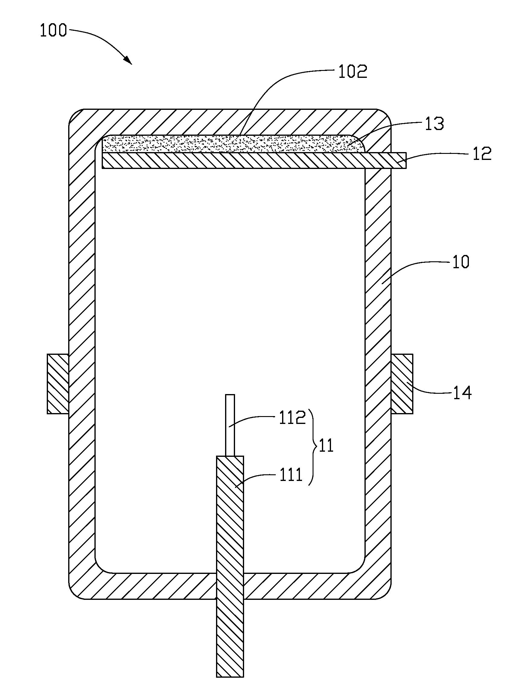
[0016]Referring to FIG. 1, a pixel tube for a field-emission illumination / display device 100 includes a sealed container 10 having a light permeable portion 102; an anode electrode 12 disposed in the sealed container 10 and adjacent to the light permeable portion; a cathode electrode 11 arranged in the sealed container 10 and including a cathode supporter 111 and a carbon nanotube yarn 112 disposed thereon, the carbon nanotube yarn 112 extending toward the anode electrode 12 for emitting electrons therefrom, one end of the cathode supporter 111 is inside the sealed container 10 (i.e., extends into the interior of the sealed container 10), an intermediate portion of the cathode supporter 111 is hermetically sealed in an end wall of the sealed container 10, and the other end of the cathode supporter 111 extends to the outside of the se...


PUM


Abstract

A pixel tube for a field-emission illumination/display device includes a sealed container, an anode electrode, a cathode electrode and a shielding electrode. The sealed container has a light permeable portion. The anode electrode is disposed in the sealed container and adjacent to the light permeable portion. The cathode electrode is arranged in the sealed container facing the anode electrode and includes a cathode supporter and a carbon nanotube yarn, the carbon nanotube yarn attached to the cathode supporter and extending toward the anode electrode for emitting electrons therefrom. The shielding electrode is disposed on a surface of the sealed container and surrounds/encircles the carbon nanotube yarn.

Description

BACKGROUND[0001]1. Field of the Invention[0002]The invention relates to field emission display devices and, more particularly, to a pixel tube for a field emission display device.[0003]2. Discussion of Related Art[0004]Field-emission illumination / display devices are based on emission of electrons in a vacuum. Electrons are emitted from micron-sized (or less) tips in a strong electric field, and the electrons are accelerated and collide with a fluorescent material. The fluorescent material then emits visible light. Such field emission devices are thin, are light weight, and provide high levels of brightness.[0005]Conventionally, a material of the tips has generally been selected from the group consisting of molybdenum (Mo) and silicon (Si). With the development of nano-technology, carbon nanotubes (CNTs) have also been used for the tips of the field emission devices.[0006]A conventional pixel tube includes a cathode electrode and an anode electrode arranged over the cathode electrode...

Claims


Application Information

Patent Timeline
IPC IPC(8): H01J1/62
CPCH01J29/862H01J2329/0455H01J2201/30469H01J31/123
Inventor YANG, YUAN-CHAOLIU, LIANGJIANG, KAI-LIFAN, SHOU-SHAN
Owner TSINGHUA UNIV
Why Eureka
Try Eureka