

Cushioning apparatus
a technology of cushioning apparatus and seat, which is applied in the direction of fluid mattresses, chairs, sofas, etc., can solve the problems of affecting user comfort, affecting the comfort of users, and affecting the appearance of covers that are bulky and overweight, so as to achieve greater pressure and temperature sensitivity
- Summary
- Abstract
- Description
- Claims
- Application Information
AI Technical Summary
Benefits of technology
Problems solved by technology
Method used
Image

Examples
Embodiment Construction
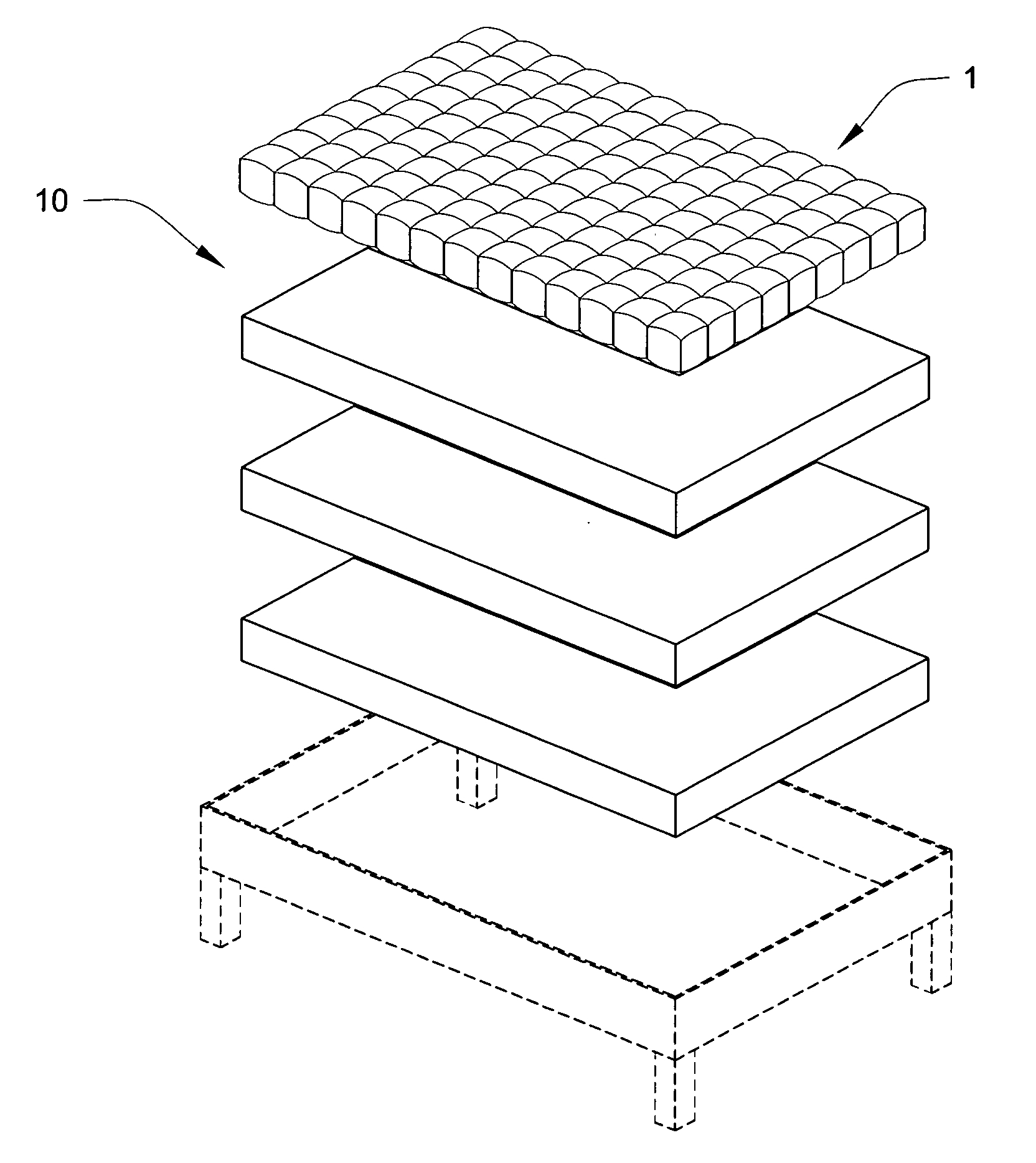
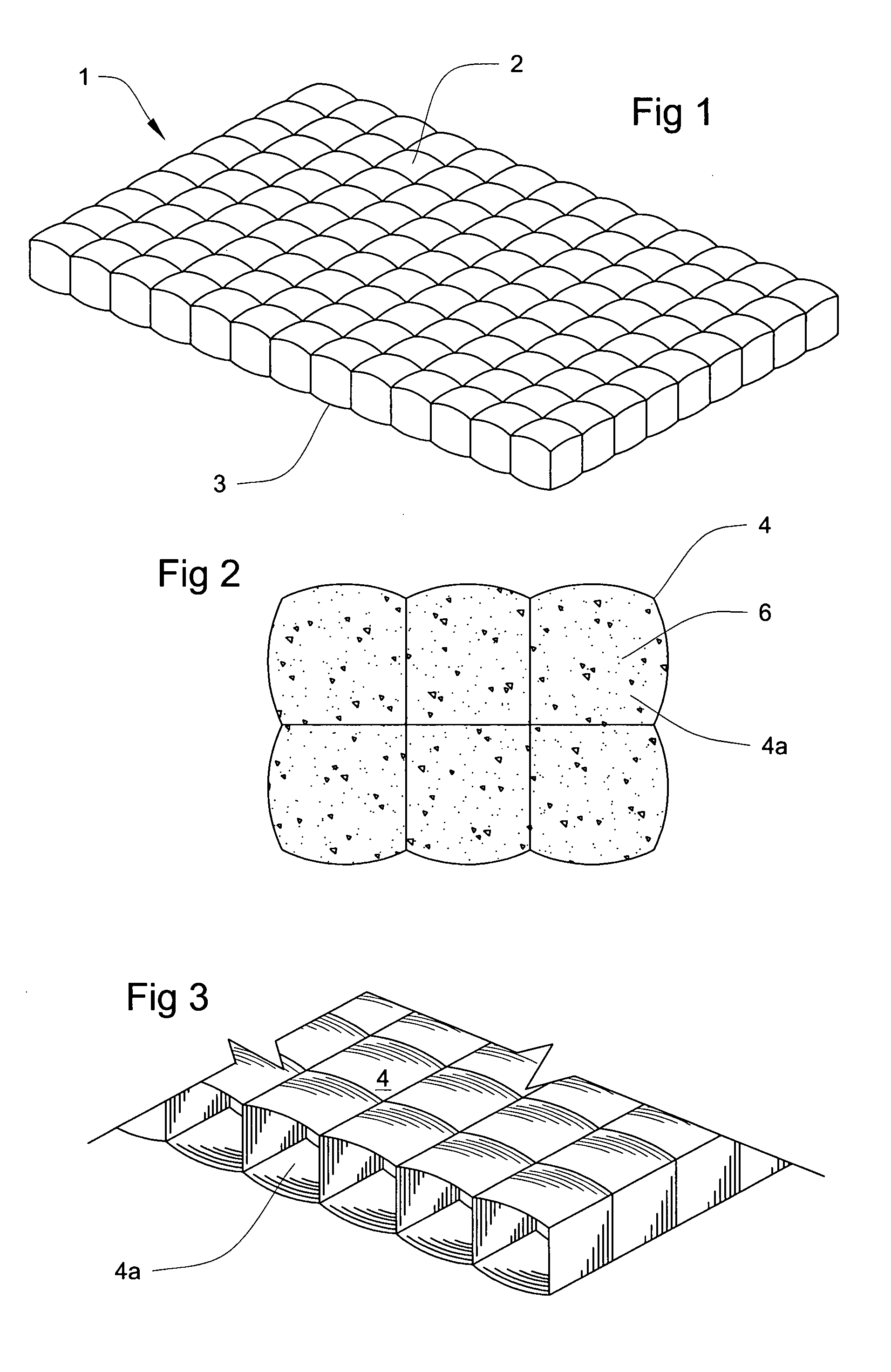
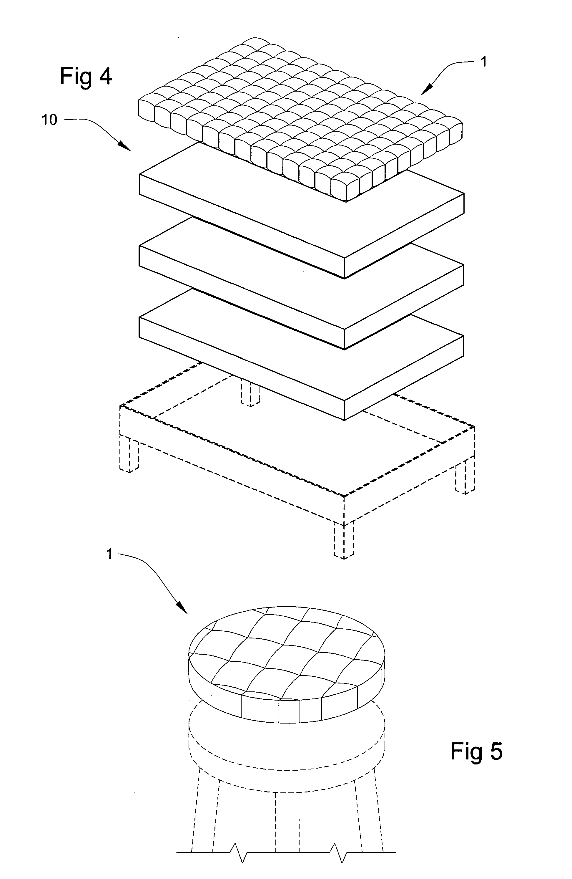
[0018]An improved duvet-design cushioning apparatus 1 to be utilized as a topper or cover for mattresses and / or box spring combinations, chairs, stools, and the like is disclosed. Although there exist a variety of different duvet designs that differ in manufacture and construction details, cushioning apparatus 1 of the present invention is not limited to a particular duvet design or duvet construction. In general, and as used herein, “duvet” refers to two pieces of any type of textile or non-woven material that are sewn together in a desired shape and provided with individual pockets or chambers having a filling. In a preferred embodiment, cushioning apparatus 1 of the present invention comprises an upper panel 2 and a lower panel 3. Apparatus 1 may optionally comprise side panels, in accordance with desire. Upper and lower panels 2 and 3 are preferably of suitable size and configuration, e.g. round, rectangular, square, etc., to correspond to a given sleeping or sitting surface. Th...
PUM
| Property | Measurement | Unit |
|---|---|---|
| density | aaaaa | aaaaa |
| density | aaaaa | aaaaa |
| length | aaaaa | aaaaa |
Abstract
Description
Claims
Application Information