
Integrated housing for fan and alternate flow check valve

Active Publication Date: 2009-01-22
HAMILTON SUNDSTRAND CORP
View PDF19 Cites 0 Cited by
  • Summary
  • Abstract
  • Description
  • Claims
  • Application Information

AI Technical Summary

Benefits of technology

[0006]In one embodiment of this invention, a fan is positioned within a housing for rotation about an axis. Check valves for selectively allowing or blocking alternate flow of air are provided circumferentially around the axis

Problems solved by technology

However, when the aircraft is in flight, the movement of the aircraft will drive the air and the fan may be stopped.
The result has been somewhat cumbersome and unduly large.

Method used


Image

  • Integrated housing for fan and alternate flow check valve
  • Integrated housing for fan and alternate flow check valve

Examples


Embodiment Construction

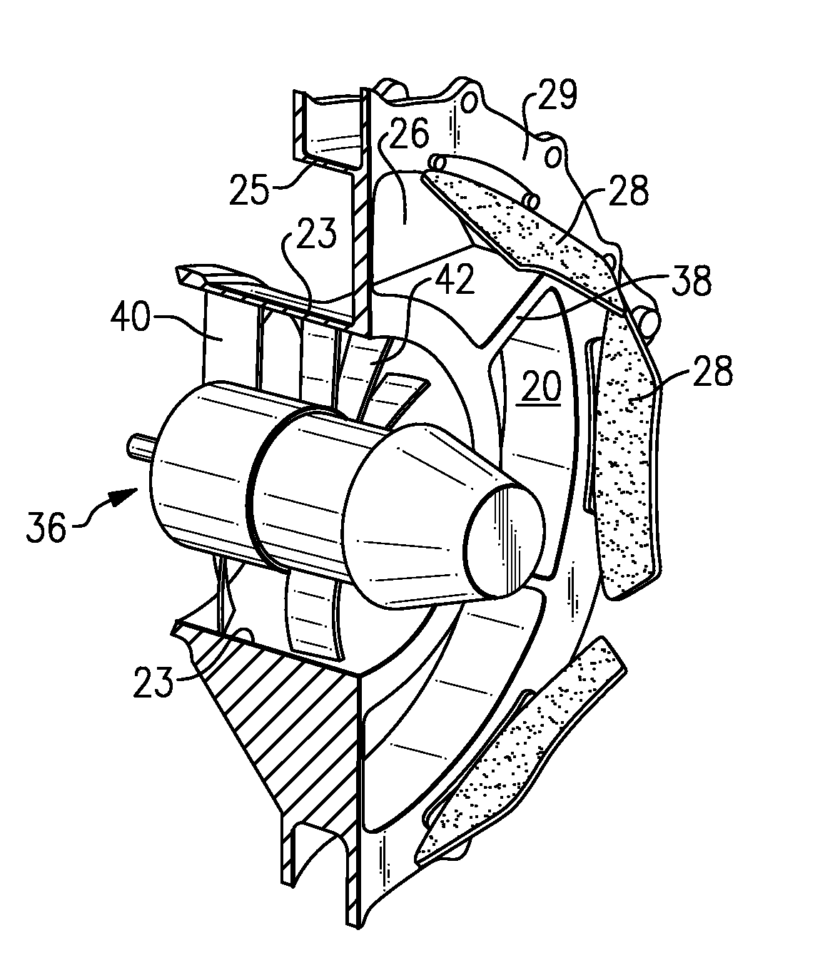
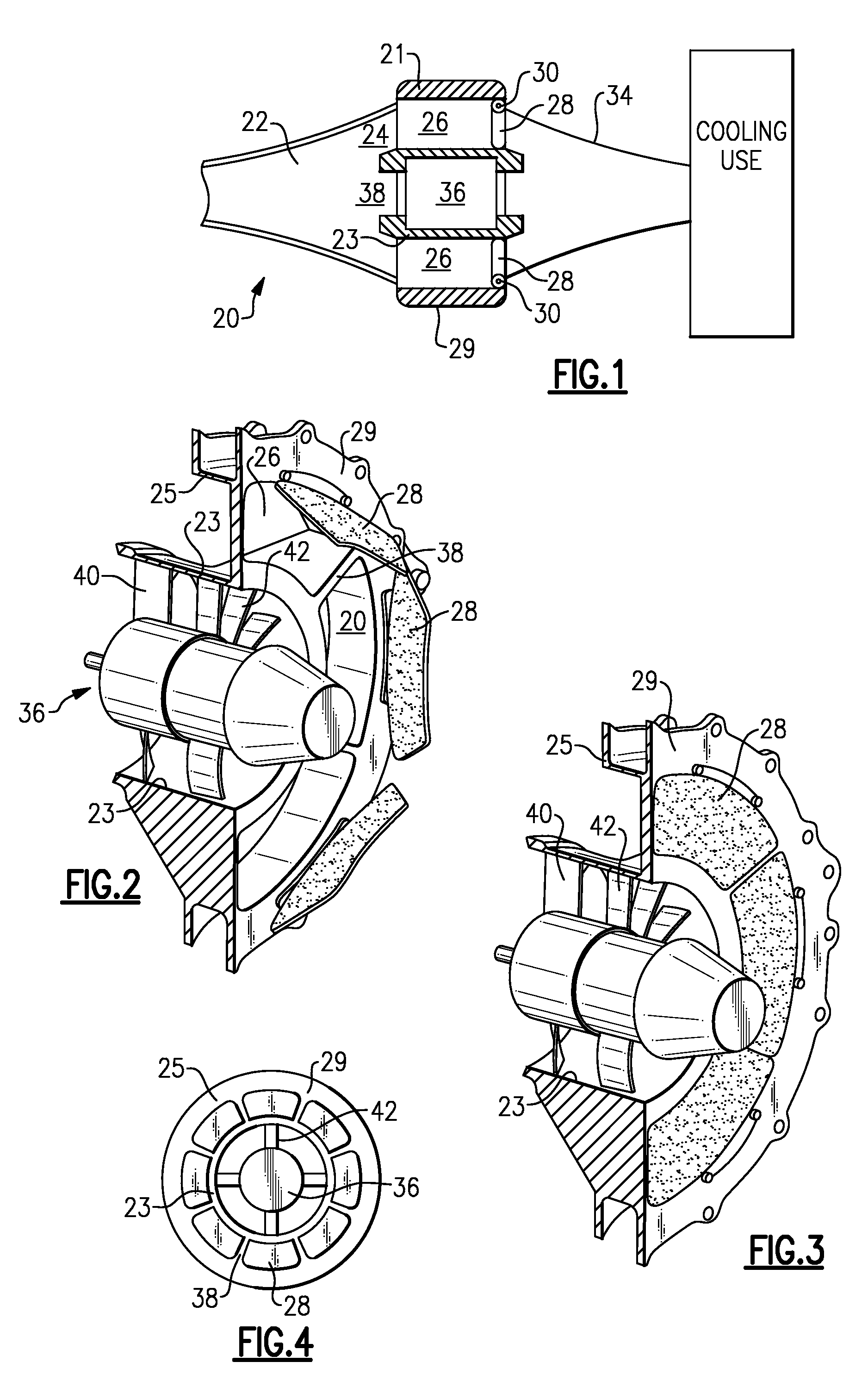
[0012]An arrangement 20 is illustrated in FIG. 1 for supplying air to a cooling use. Air is taken from a conduit 22, which may actually communicate with ambient air, such as from the exterior of an aircraft or other vehicle. Air from conduit 22 may be moved into conduit 24, which may be generally annular and surrounds a central conduit 38. The air flowing through the conduit 24 flows into a plurality of flow passages 26 which are selectively closed by check valves 28, for example hingedly attached at 30 to a housing 29. Housing 29 is shown to include a radially inner wall 23, and a radially outer wall 21. While flap check valves 28 are shown, which are hingedly attached to the housing 29, any other type of valve structure would come within the scope of this invention. Other types of pivoting check valves can be utilized, and check valves that move in a direction other than about a pivot point, such as away from a valve seat, can also be used.

[0013]A fan 36 selectively drives air fro...


PUM


Abstract

A single housing is utilized to mount both an internal fan, and an external alternate flow passage closed by a check valve. The alternate flow passage is defined between an inner and outer wall of the single housing, while the fan is mounted within the inner wall.

Description

BACKGROUND OF THE INVENTION[0001]This application relates to a housing for a fan, which has alternate flow passages closed by check valves integrated into the housing.[0002]Aircraft are becoming provided with more and more sophisticated electronic components. Cooling schemes are necessary for cooling these components.[0003]One known cooling scheme is to move cooling air over a liquid which in turn cools the electronics. The cooling air may be taken from an area outside of the aircraft, and returned to the outside of the aircraft after cooling.[0004]The prior art has typically moved this air by an alternative flow arrangement wherein a fan is provided to pull air from outside of the aircraft, and over the fluid to be cooled, through a first conduit. A second wholly separate and branched conduit is also provided, and has a check valve closure.[0005]When the aircraft is on the ground, the fan must be utilized to move the air. However, when the aircraft is in flight, the movement of the...

Claims


Application Information

Patent Timeline
IPC IPC(8): F04D29/40F24F7/007
CPCF04D25/14F04D29/601F04D29/582
Inventor DOHERTY, JAMES
Owner HAMILTON SUNDSTRAND CORP
Learn More