Eureka AIR delivers breakthrough ideas for toughest innovation challenges, trusted by R&D personnel around the world.

Drain plug for carrier assembly

a carrier assembly and drain plug technology, applied in the direction of transportation and packaging, process and machine control, instruments, etc., can solve the problems of churning loss, premature wear, and loss of efficiency at the gear assembly, and achieve the effect of reducing churning loss and high running level

Active Publication Date: 2009-01-29
ARVINMERITOR TECH
View PDF8 Cites 8 Cited by
  • Summary
  • Abstract
  • Description
  • Claims
  • Application Information

AI Technical Summary

Benefits of technology

The patent describes a drain plug used to control fluid flow in a carrier assembly. The drain plug can be adjusted to control the rate of fluid flow between a reservoir and a sump in the assembly. The drain plug is attached to the carrier housing and extends into a channel to provide a fluid flow restriction. The drain plug can be changed to achieve different fluid flow rates, and multiple drain plugs can be used to achieve the desired flow rate. The use of a separate reservoir area reduces churning losses and allows for a high running level to feed other lubricating passages. These features improve the performance and efficiency of the carrier assembly.

Problems solved by technology

One problem with current configurations is efficiency losses at the gear assembly that result from churning of the lubricating fluid.
Further, excessive churning of the lubricating fluid causes foaming of the fluid and can lead to inadequate lubrication coverage for gear components, resulting in premature wear.
The effects of churning losses are even greater when narrow package carrier configurations are used.

Method used


Image

  • Drain plug for carrier assembly
  • Drain plug for carrier assembly
  • Drain plug for carrier assembly

Examples


Embodiment Construction

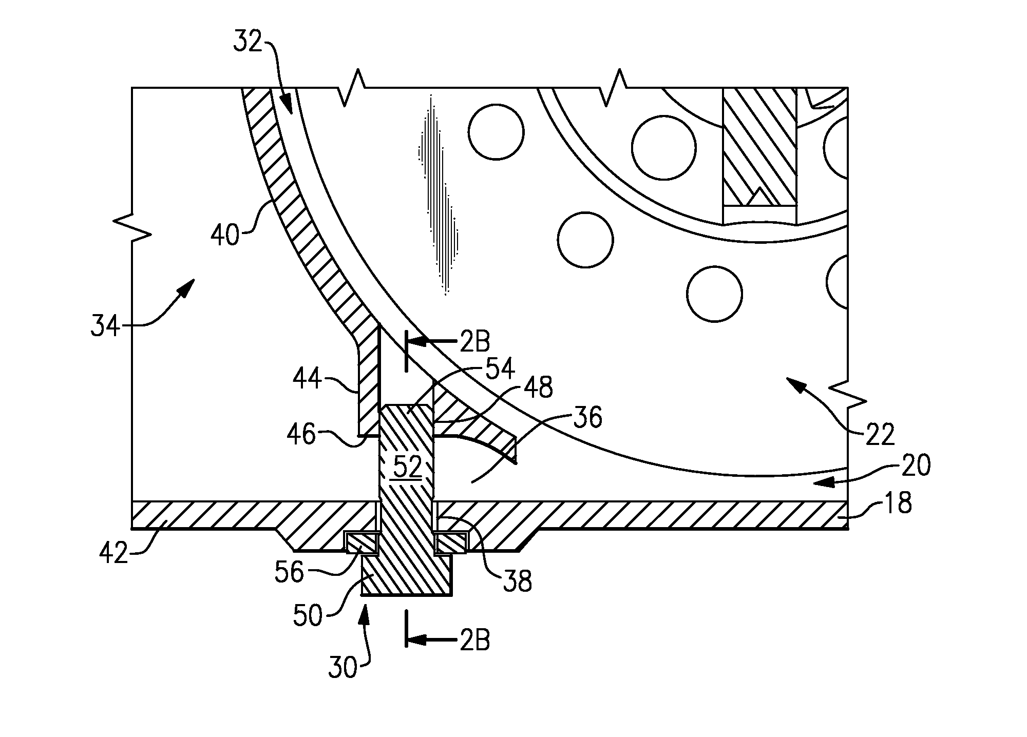
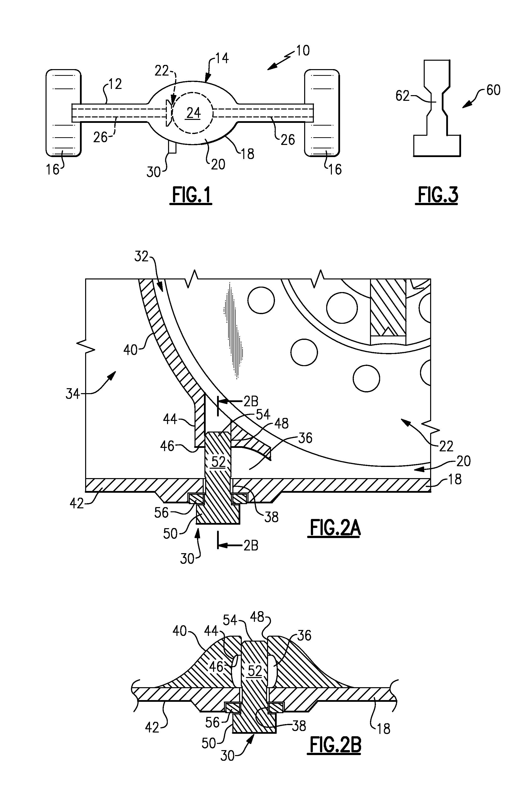
[0017]A drive axle 10, shown in FIG. 1, includes an axle housing 12 with a carrier 14 that is used to drive a pair of laterally spaced vehicle wheels 16. The carrier 14 includes a carrier housing 18 that can be formed as part of the axle housing 12 or which can be a separate housing that is attached to the axle housing 12. The carrier housing 18 defines an internal cavity 20 that receives a gear assembly 22. In the example shown, the gear assembly 22 comprises a differential 24 (shown schematically) that receives driving input from a ring and pinion gear set (not shown). The differential 24 is coupled to drive a pair of axle shafts 26, which in turn drive the vehicle wheels 16.

[0018]The internal cavity 20 is partially filled with a lubricating fluid to lubricate the gear assembly 22. A drain plug 30 is mounted to the carrier housing 18 to allow the lubricating fluid to be drained from the carrier housing 18. The drain plug 30 and carrier housing 18 are configured to reduce churning ...


PUM


Abstract

A drain plug for a carrier assembly is used to control fluid flow from a reservoir to a sump. The carrier assembly includes a carrier housing with an internal cavity that houses a gear assembly. The sump is located within the internal cavity to lubricate the gear assembly. The reservoir is separated from the sump by a channel. The drain plug is attached to the carrier housing, and extends into the channel, to provide a fluid flow restriction between the reservoir and the sump.

Description

TECHNICAL FIELD[0001]The subject invention relates to a drain plug that is used to control fluid flow within a carrier assembly.BACKGROUND OF THE INVENTION[0002]Carrier assemblies for drive axles include a carrier housing with an internal cavity that receives a gear assembly. The gear assembly drives output shafts, which in turn are coupled to drive vehicle wheels. The gear assembly must be properly lubricated to avoid premature wear and failure. The internal cavity is filled with to certain level with lubricating fluid, which lubricates the gear assembly as gear components rotate within the internal cavity. A drain plug is installed within the carrier housing at the internal cavity to allow lubricating fluid to be filled into, and drained from, the internal cavity.[0003]One problem with current configurations is efficiency losses at the gear assembly that result from churning of the lubricating fluid. Further, excessive churning of the lubricating fluid causes foaming of the fluid ...

Claims


Application Information

Patent Timeline
Patent Type & Authority Applications(United States)
IPC IPC(8): F16N31/00B60R17/00F16H57/04
CPCF16H57/0447F16H57/0457F16H2057/02052F16H57/02Y10T74/2189Y10T74/2188F16H57/0408F16H57/0453F16H57/0409F16H57/0483
Inventor MARTIN, III, ROBERT J.HAYES, BRIAN DAVID
Owner ARVINMERITOR TECH
Why Eureka
Eureka Blog
Learn More