
Load Spreader Bar System

a spreader bar and load technology, applied in the direction of load-engaging elements, connections, transportation and packaging, etc., can solve the problems of prior art assemblies that have been known to fail, the installation or detachment of items for use in different lifts is a time-consuming and laborious process, and the use of enormous pressure on the spreader bar system

Active Publication Date: 2009-03-05
TANDEMLOC
View PDF25 Cites 13 Cited by
  • Summary
  • Abstract
  • Description
  • Claims
  • Application Information

AI Technical Summary

Benefits of technology

"The present invention provides an improved spreader bar assembly that solves several disadvantages of prior art assemblies. The assembly includes an end cap with a flange and a shackle connection part, and an insertion part with a shoulder for abutment with the spreader pipe. The end cap may have a fastener mechanism for securing to different spreader pipes. The assembly may also include a groove that captures the end of the spreader pipe, and a pipe reducing connection sleeve for use in a spreader bar assembly. The technical effects of the invention include improved connection between the spreader pipes, reduced size of the assembly, and increased efficiency of the spreader bar assembly."

Problems solved by technology

Generally, the installation or detachment of items for use in different lifts is a time consuming and laborious process.
Additionally, it is known that many of these prior art assemblies are made in permanent assemblies, such as end caps welded to spreader pipes, or in a manner that is difficult to assemble / disassemble (a multitude of bolts and nuts, etc.).
Even further, it is known that tremendous pressures can be applied to the spreader bar systems during use and the prior art assemblies have been known to fail under such pressures, especially at mid-span joints, due to improper seating of junctions.

Method used


Image

  • Load Spreader Bar System
  • Load Spreader Bar System
  • Load Spreader Bar System

Examples


Embodiment Construction

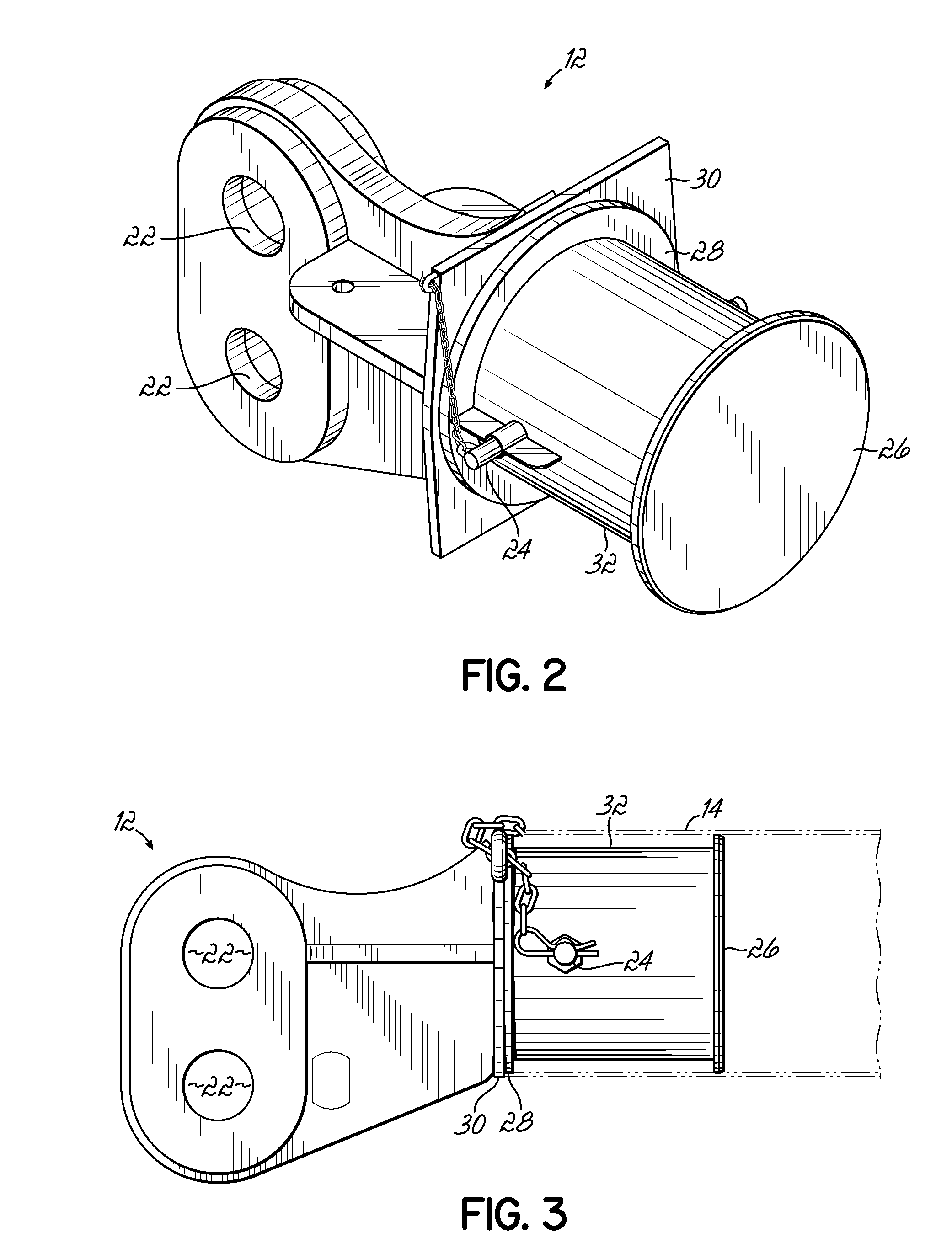
[0032]Embodiments consistent with the underlying principles of the present invention include an improved spreader bar assembly, and more specifically, an end cap and pipe connection sleeve that increase the efficiency of using and assembling a spreader bar assembly. A spreader bar assembly may include an end cap having a shackle connection part and an insertion part adapted for detachable connection to a spreader pipe. A connection sleeve may include multiple insertion ends for respective connection to respective spreader pipes. Where so configured, the pipes may have different diameters. Embodiments may provide a system to quickly connect or disconnect the end lift points with the pipe connection and reducer sleeves.

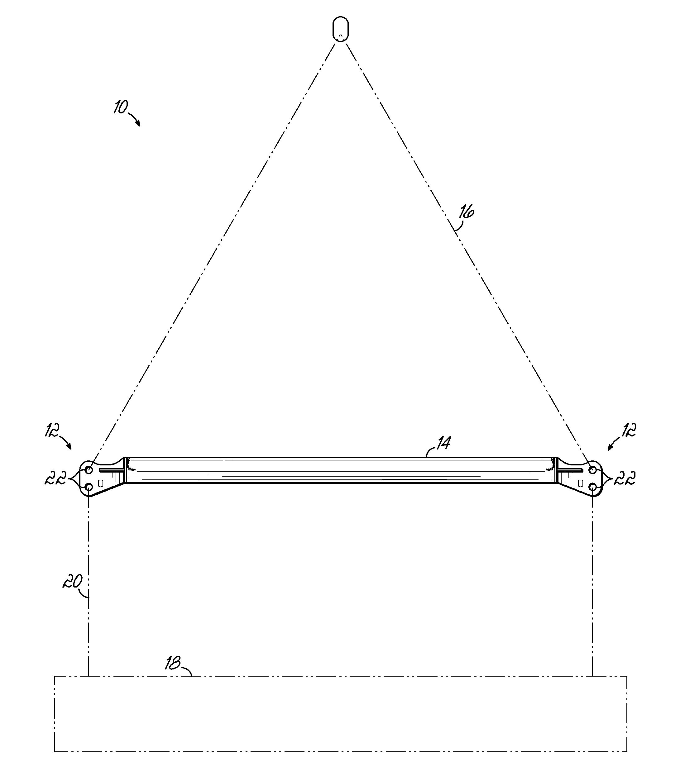
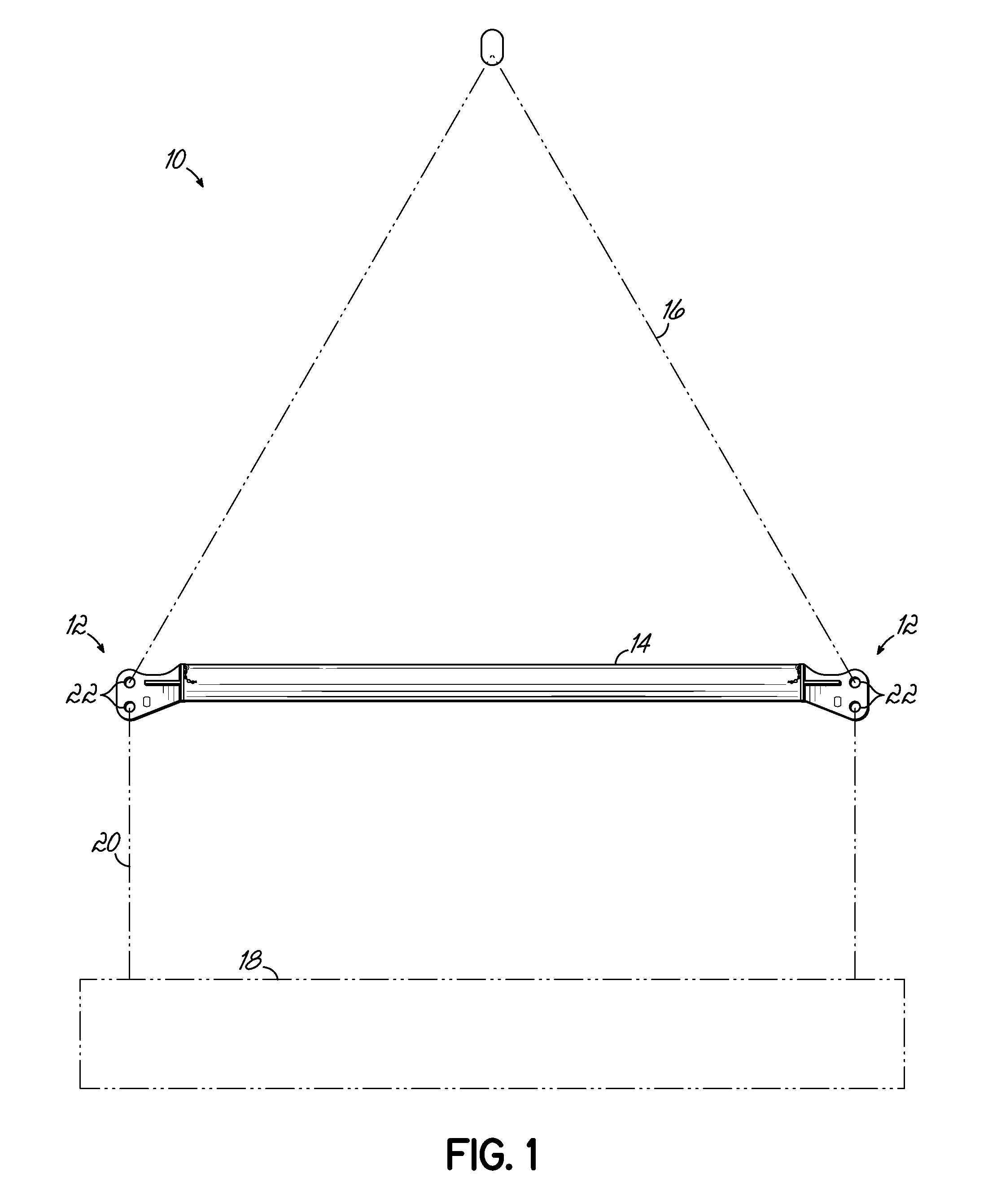
[0033]In a first embodiment, FIG. 1 shows a spreader bar assembly 10 comprising an end cap 12 and a single spreader bar 14. The spreader bar assembly 10 typically attaches to some lift mechanism, such as a crane, via Y-cables 16. The cables 16 and the assembly 10 may be...


PUM


Abstract

A spreader bar assembly includes an end cap having a shackle connection part and an insertion part adapted for detachable connection to a spreader pipe. A connection sleeve may include multiple insertion ends for respective connection to respective spreader pipes. Where so configured, the pipes may have different diameters.

Description

CROSS REFERENCE TO RELATED APPLICATION[0001]This application is related to and claims priority to U.S. Provisional Application Ser. No. 60 / 970,041, filed Sep. 5, 2007, the disclosure of which is specifically incorporated by reference herein.FIELD OF THE INVENTION[0002]The present invention relates generally to load spreader bar systems typically used in the shipping and container industry for the lifting and supporting of cargo.BACKGROUND OF THE INVENTION[0003]In the related and relevant “below the hook” art technology, shipping containers and similar loads are typically lifted by means of a “spreader bar” assembly that can generally consist of end caps that insert into each end of a pipe segment wherein the end caps are connected by a “Y” cable to a crane or other lifting mechanism. Spreader bar assemblies of various lengths can be made by using pipe connections in-between different lengths of pipe.[0004]A variety of prior art patent documents relate to spreader bar assemblies or c...

Claims


Application Information

Patent Timeline
Patent Type & Authority Applications(United States)
IPC IPC(8): B66C1/22B66C1/00
CPCY10T403/64B66C1/22F16B2200/50
Inventor DI MARTINO, JOHN MICHAEL
Owner TANDEMLOC
Learn More