Image display unit and face piece unit

a technology of image display and face piece, which is applied in the direction of electrical apparatus casings/cabinets/drawers, television systems, instruments, etc., can solve problems such as interference with the use of image display apparatus

Inactive Publication Date: 2009-03-05
KONICA MINOLTA INC
View PDF2 Cites 29 Cited by
  • Summary
  • Abstract
  • Description
  • Claims
  • Application Information

AI Technical Summary

Benefits of technology

[0011]According to the present invention, since the face contact portion of the supporting member is formed so as to be symmetric with respect to a plane perpendicular to a line connecting the viewer's eyes when the supporting member fits into the face piece, it is possible to prevent the image displ

Problems solved by technology

However, conventional HMDs including the HMD disclosed in JP-A-H11-296095 do not have a construction intended to be used in combi

Method used


Image

  • Image display unit and face piece unit
  • Image display unit and face piece unit
  • Image display unit and face piece unit

Examples


Embodiment Construction

[0024]Hereinafter, an embodiment of the present invention will be described with reference to the drawings.

1. A Face Piece Unit

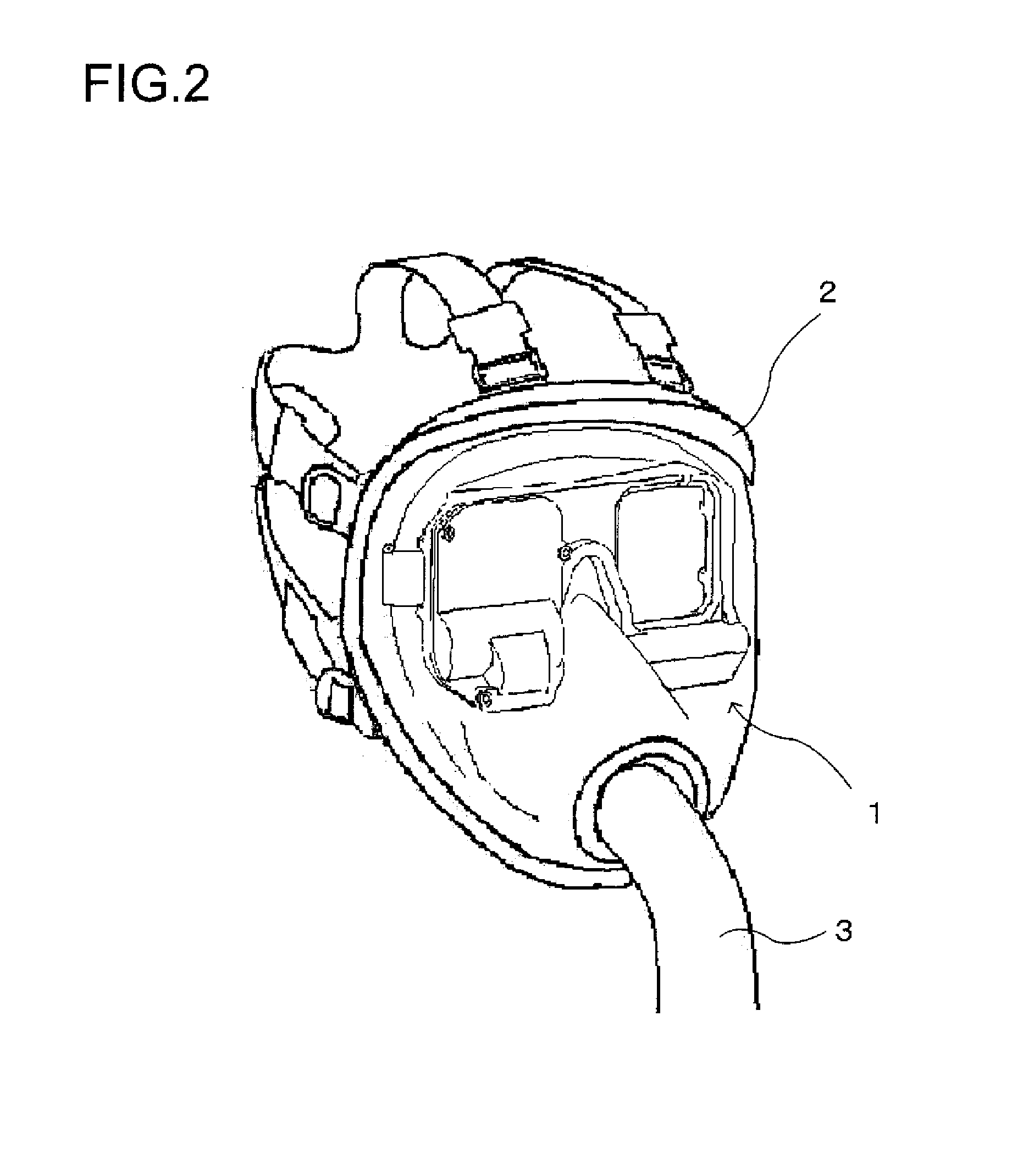
[0025]FIG. 2 is a perspective view showing an outline of the construction of a face piece unit according to the embodiment. This face piece unit is composed of an image display unit 1 and a face piece 2.

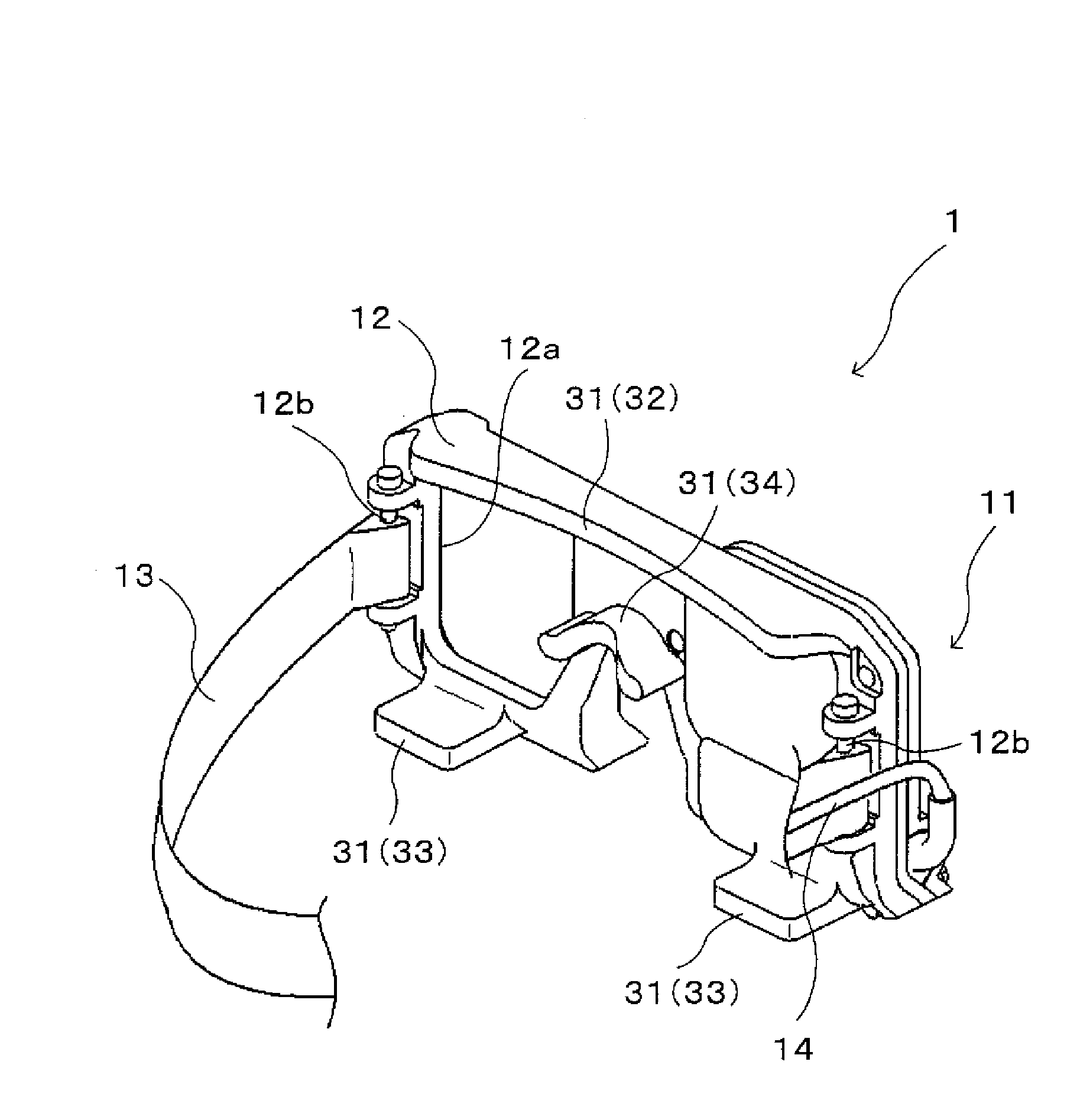
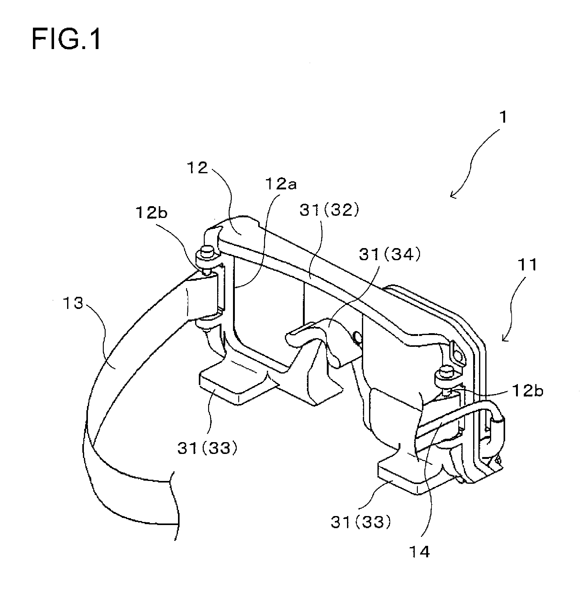
[0026]The image display unit 1 displays an image and presents the viewer with the image as a virtual image, while allowing the viewer to view an outside world image on a see-through basis. The image display unit 1 will be described in detail later.

[0027]The face piece 2 is placed on the viewer's face. In this embodiment, after the image display unit 1 is mounted on the viewer's head, the face piece 2 is placed thereon so as to cover the image display unit 1. In other words, the face piece 2 is placed on the viewer's face with an image display apparatus 11 and a supporting member 12 (of which both will be described later and are shown in FIG. 5) of the image d...


PUM


Abstract

An image display apparatus is supported by a supporting member positioned in front of the viewer's face. The supporting member is formed into a shape that allows it to fit into a face piece. Thus, the viewer is allowed to view an image displayed by the image display apparatus while wearing the face piece. Moreover, when the supporting member fits into the face piece, a face contact portion of the supporting member is held in contact with the viewer's face. At this point, since the face contact portion is formed so as to be symmetric with respect to a plane perpendicular to a line connecting the viewer's eyes, it is possible to easily prevent the supporting member from becoming askew on the face when the supporting member fits into the face piece. This helps prevent the image display apparatus supported by the supporting member from becoming askew while operations are carried out with the face piece placed on the face.

Description

[0001]This application is based on Japanese Patent Application No. 2007-229672 filed on Sep. 5, 2007, the contents of which are hereby incorporated by reference.BACKGROUND OF THE INVENTION[0002]1. Field of the Invention[0003]The present invention relates to an image display unit having an image display apparatus supported in front of the viewer's eye by a supporting member, and a face piece unit composed of the image display unit and a face piece placed on the viewer's face.[0004]2. Description of Related Art[0005]A head-mounted image display apparatus that is mounted on the viewer's head and that projects a virtual image of the image generated by the display device onto the viewer's pupil is generally known as a so-called HMD (head-mounted display). Among these devices, an HMD disclosed in JP-A-H11-296095 has a dustproof member arranged between a holder that holds an LCD serving as a display device and an entrance surface of a prism used in an eyepiece optical system, that is, the ...

Claims


Application Information

Patent Timeline
IPC IPC(8): H05K7/00
CPCA61F9/029B63C11/12B63C2011/121H04N5/7491G02B2027/0174G02B2027/0181H04N5/74G02B27/0176
Inventor YAMAGUCHI, HIROSHI
Owner KONICA MINOLTA INC
Why Eureka
Try Eureka