Method for encoding and decoding video signal

a video signal and video technology, applied in signal generators with optical-mechanical scanning, color televisions with bandwidth reduction, etc., can solve the problems of time delay, difficult to allocate a broadband available, complex hardware devices and algorithms, etc., and achieve the effect of improving coding efficiency

Inactive Publication Date: 2009-03-05
LG ELECTRONICS INC
View PDF8 Cites 22 Cited by
  • Summary
  • Abstract
  • Description
  • Claims
  • Application Information

AI Technical Summary

Benefits of technology

[0022]Accordingly, the present invention has been made to solve the above-mentioned problems occurring in the prior art, and an object of the present invention is to provide a method for encoding a video signal by applying a residual prediction mode for a macro block of an enhanced layer even if a frame temporally simultaneous with a frame of the enhanced layer does not exist in a base layer and a method for decoding the encoded video signal to improve coding efficiency.

Problems solved by technology

It is difficult to allocate a broadband available for TV signals to wirelessly transmitted / received digital video signals wirelessly transmitted / received from / in a portable phone and a notebook computer, which have been extensively used, and a mobile TV and a hand held PC, which are expected to be extensively used in the future.
Therefore, the portable devices must be equipped with video data having various qualities obtained through the combination of various parameters including the number of transmission frames per second, resolution, and the number of bits per pixel with respect to one video source, burdening content providers.
However, since the above-described procedure necessarily requires trans-coding (decoding+scaling+encoding), the procedure causes a time delay when providing the video requested by the portable devices.
In addition, the transcoding requires complex hardware devices and algorithms due to the variety of a target encoding.
However, since a residual block of the base layer corresponding to the second residual block of the enhanced layer R_MB_2 may not exist, it is difficult to find a predicted video based on the residual block of the base layer.
In addition, the residual prediction mode cannot be applied even if a residual frame temporally simultaneous with a frame including a macro block of the enhanced layer does not exist in the base layer.
Accordingly, it is difficult to expect the improvement of coding efficiency.

Method used


Image

  • Method for encoding and decoding video signal
  • Method for encoding and decoding video signal
  • Method for encoding and decoding video signal

Examples


Embodiment Construction

[0039]Hereinafter, preferred embodiments of the present invention will be described with reference to the accompanying drawings. In the following description and drawings, the same reference numerals are used to designate the same or similar components, and so repetition of the description on the same or similar components will be omitted.

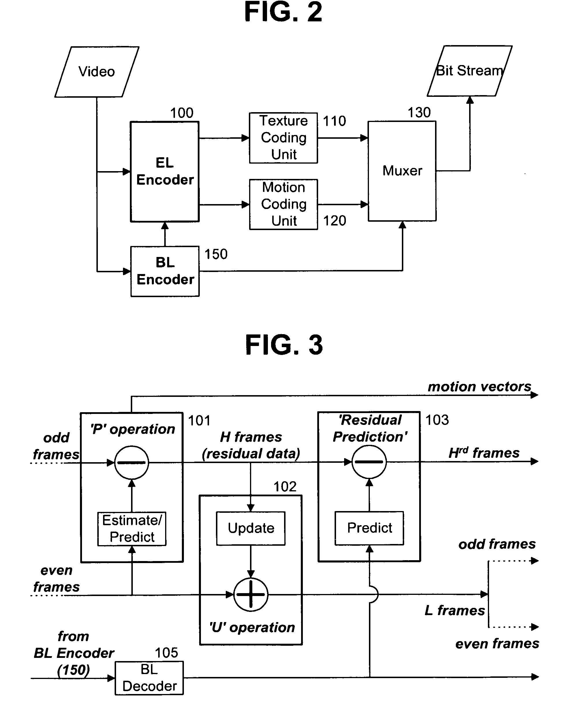
[0040]FIG. 2 is a block diagram illustrating the structure of a video signal encoding device employing a scalable coding scheme for a video signal according to the present invention.

[0041]The video signal encoding device shown in FIG. 2 includes an enhanced layer (EL) encoder 100 for scalably encoding an input video signal based on a macro block through a Motion Compensated Temporal Filter (MCTF) scheme and generating suitable management information, a texture coding unit 110 for converting the encoded data of each macro block into a compressed bit string, a motion coding unit 120 for coding motion vectors of a video block obtained from the EL enco...


PUM


Abstract

Disclosed is a method for encoding a decoding a video signal. In the procedure of encoding the video signal, when a frame temporarily simultaneous with a frame including a macro block of an enhanced layer which will obtain a prediction video does not exist in a base layer, the macro block is encoded based on difference values of residual data using corresponding residual blocks in a past frame and a future frame of the base layer which are residual data corresponding to image difference values and using a residual block for the macro block of the enhanced layer. In another embodiment, the macro block is encoded based on difference values of residual data using corresponding residual blocks in a past frame and a future frame of the enhanced layer and the residual block for the macro block. Accordingly, a residual prediction mode is applied for a macro block of an enhanced layer even if a frame temporally simultaneous with a frame of the enhanced layer does not exist in a base layer, thereby improve coding efficiency.

Description

DOMESTIC PRIORITY INFORMATION[0001]This application claims priority under 35 U.S.C. §119 on U.S. Provisional Application No. 60 / 632,994, filed on Dec. 6, 2004; the entire contents of which are hereby incorporated by reference.[0002]This is a continuation application of application Ser. No. 11 / 293,167 filed Dec. 5, 2005, the entire contents of which are hereby incorporated by reference.FOREIGN PRIORITY INFORMATION[0003]This application claims priority under 35 U.S.C. §119 on Korean Patent Application No. 10-2005-0057565, filed on Jun. 30, 2005, the entire contents of which are hereby incorporated by reference.BACKGROUND OF THE INVENTION[0004]1. Field of the Invention[0005]The present invention relates to a method for encoding and decoding a video signal, and more particularly to a method for encoding a video signal by employing a residual prediction mode and decoding the encoded video data.[0006]2. Description of the Prior Art[0007]It is difficult to allocate a broadband available fo...

Claims


Application Information

Patent Timeline
Patent Type & Authority Applications(United States)
IPC IPC(8): H04N7/32H04N19/30
CPCH04N19/105H04N19/176H04N19/137H04N19/577H04N19/33H04N19/31H04N19/59H04N19/187H04N19/30
Inventor PARK, SEUNG WOOKPARK, JI HOJEON, BYEONG MOON
Owner LG ELECTRONICS INC
Why Eureka
Try Eureka