Moving picture coding method and moving picture decoding method for performing inter picture prediction coding and inter picture prediction decoding using previously processed pictures as reference pictures

a technology of moving picture and prediction, applied in the field of moving picture prediction coding and moving picture decoding methods, can solve the problems of reducing coding efficiency, current b-picture and reference picture may be long,

Inactive Publication Date: 2008-03-13
PANASONIC INTELLECTUAL PROPERTY CORP OF AMERICA
View PDF23 Cites 90 Cited by
  • Summary
  • Abstract
  • Description
  • Claims
  • Application Information

AI Technical Summary

Benefits of technology

[0033] Therefore, when the direct mode is selected, since a first motion vector of a picture which is dec

Problems solved by technology

However, when B-pictures are coded using inter picture prediction with reference to I and P-pictures, the temporal dis

Method used


Image

  • Moving picture coding method and moving picture decoding method for performing inter picture prediction coding and inter picture prediction decoding using previously processed pictures as reference pictures
  • Moving picture coding method and moving picture decoding method for performing inter picture prediction coding and inter picture prediction decoding using previously processed pictures as reference pictures
  • Moving picture coding method and moving picture decoding method for performing inter picture prediction coding and inter picture prediction decoding using previously processed pictures as reference pictures

Examples


first embodiment

[0057]FIG. 3 is a block diagram showing the structure of an embodiment of the moving picture coding apparatus using the moving picture coding method according to the present invention.

[0058] As shown in FIG. 3, the moving picture coding apparatus includes a reordering memory 101, a difference calculation unit 102, a residual error coding unit 103, a bit stream generation unit 104, a residual error decoding unit 105, an addition unit 106, a reference picture memory 107, a motion vector estimation unit 108, a mode selection unit 109, a coding control unit 110, switches 111˜115 and a motion vector storage unit 116.

[0059] The reordering memory 101 stores moving pictures inputted on a picture-to-picture basis in display order. The coding control unit 110 reorders the pictures stored in the reordering memory 101 in coding order. The coding control unit 110 also controls the operation of the motion vector storage unit 116 for storing motion vectors.

[0060] Using the previously coded and ...

second embodiment

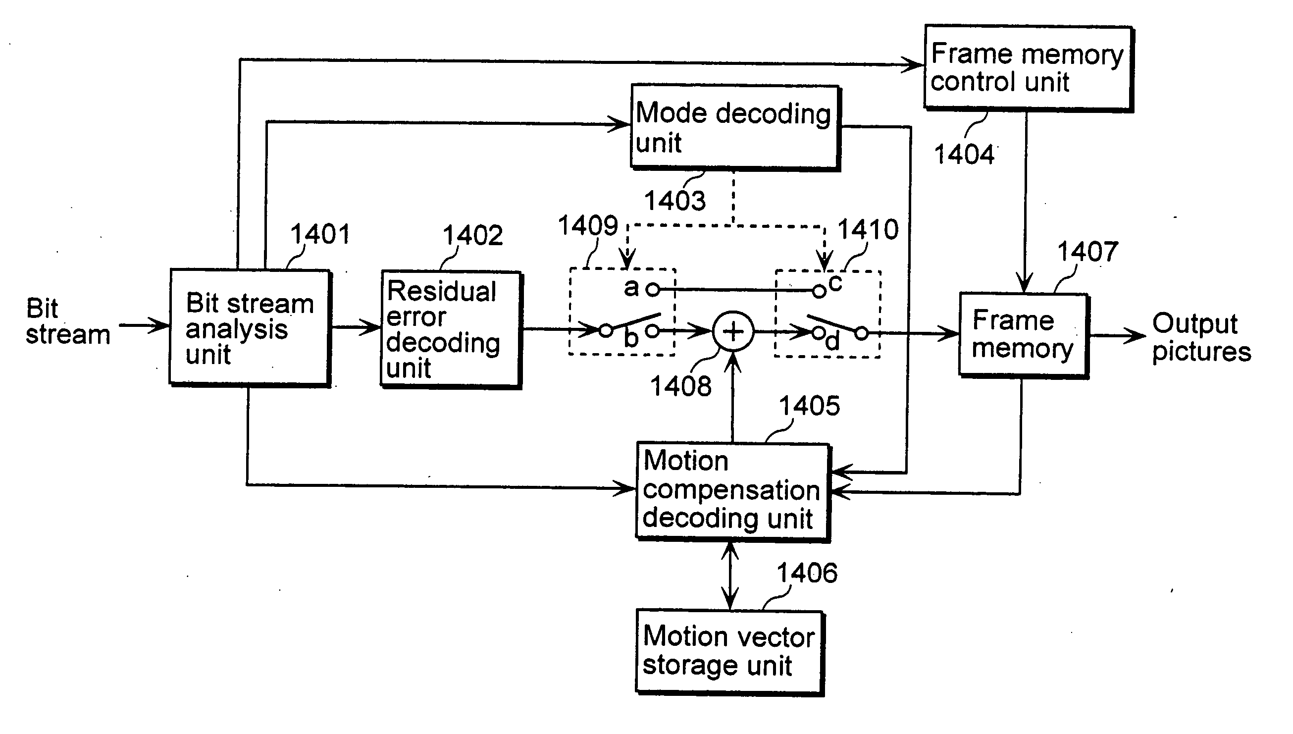
[0173]FIG. 16 is a block diagram showing a structure of a moving picture decoding apparatus using a moving picture decoding method according to an embodiment of the present invention.

[0174] As shown in FIG. 16, the moving picture decoding apparatus includes a bit stream analysis unit 1401, a residual error decoding unit 1402, a mode decoding unit 1403, a frame memory control unit 1404, a motion compensation decoding unit 1405, a motion vector storage unit 1406, a frame memory 1407, an addition unit 1408 and switches 1409 and 1410.

[0175] The bit stream analysis unit 1401 extracts various types of data such as coding mode information and motion vector information from the inputted bit stream. The residual error decoding unit 1402 decodes the residual error coded data inputted from the bit stream analysis unit 1401 and generates residual error image data. The mode decoding unit 1403 controls the switches 1409 and 1410 with reference to the coding mode information extracted from the b...

third embodiment

[0240] If a program for realizing the structures of the moving picture coding method or the moving picture decoding method as shown in the above embodiments is recorded on a memory medium such as a flexible disk, it becomes possible to perform the processing as shown in these embodiments easily in an independent computer system.

[0241]FIG. 17 is an illustration showing the case where the processing is performed in a computer system using a flexible disk which stores the moving picture coding method or the moving picture decoding method of the above embodiments.

[0242]FIG. 17B shows a front view and a cross-sectional view of an appearance of a flexible disk, and the flexible disk itself, and FIG. 17A shows an example of a physical format of a flexible disk as a recording medium body. The flexible disk FD is contained in a case F, and a plurality of tracks Tr are formed concentrically on the surface of the disk in the radius direction from the periphery and each track is divided into ...


PUM


Abstract

A coding control unit (110) and a mode selection unit (109) are included. The coding control unit (110) determines the coding order for a plurality of consecutive B-pictures located between I-pictures and P-pictures so that the B-picture whose temporal distance from two previously coded pictures is farthest in display order is coded by priority, so as to reorder the B-pictures in coding order. When a current block is coded in direct mode, the mode selection unit 109 scales a forward motion vector of a block which is included in a backward reference picture of a current picture and co-located with the current block, so as to generate motion vectors of the current block, if the forward motion vector has been used for coding the co-located block.

Description

[0001] This application is a divisional application of application Ser. No. 10 / 468,119, filed Aug. 15, 2003.TECHNICAL FIELD [0002] The present invention relates to moving picture coding methods and moving picture decoding methods, and particularly to methods for performing inter picture prediction coding and inter picture prediction decoding of a current picture using previously processed pictures as reference pictures. BACKGROUND ART [0003] In moving picture coding, data amount is generally compressed by utilizing the spatial and temporal redundancies that exist within a moving picture. Generally speaking, frequency transformation is used as a method utilizing the spatial redundancies, and inter picture prediction coding is used as a method utilizing the temporal redundancies. In the inter picture prediction coding, for coding a current picture, previously coded pictures earlier or later than the current picture in display order are used as reference pictures. The amount of motion ...

Claims


Application Information

Patent Timeline
IPC IPC(8): H04N7/12H04N19/102G06T9/00H03M7/36H04N19/105H04N19/109H04N19/114H04N19/137H04N19/139H04N19/176H04N19/196H04N19/423H04N19/50H04N19/51H04N19/577H04N19/91
CPCH04N19/105H04N19/577H04N19/70H04N19/172H04N19/46H04N19/51H04N19/61H04N19/103H04N19/107H04N19/127H04N19/136H04N19/137H04N19/157H04N19/16H04N19/44H04N19/423H04N19/573H04N19/58H04N19/176
Inventor KONDO, SATOSHIKADONO, SHINYAHAGAI, MAKOTOABE, KIYOFUMI
Owner PANASONIC INTELLECTUAL PROPERTY CORP OF AMERICA
Why Eureka
Try Eureka