
Quantization-Based Data Embedding in Mapped Data

a data and mapping technology, applied in the field of multi-media signal processing, steganography and data hiding, can solve the problems of distorted samples, symbol errors, and the wrong quantizer or bin, and achieve the effect of reducing the impact of distortion, reducing symbol errors, and decoding more accurately

Inactive Publication Date: 2011-02-24
DIGIMARC CORP
View PDF70 Cites 39 Cited by
  • Summary
  • Abstract
  • Description
  • Claims
  • Application Information

AI Technical Summary

Benefits of technology

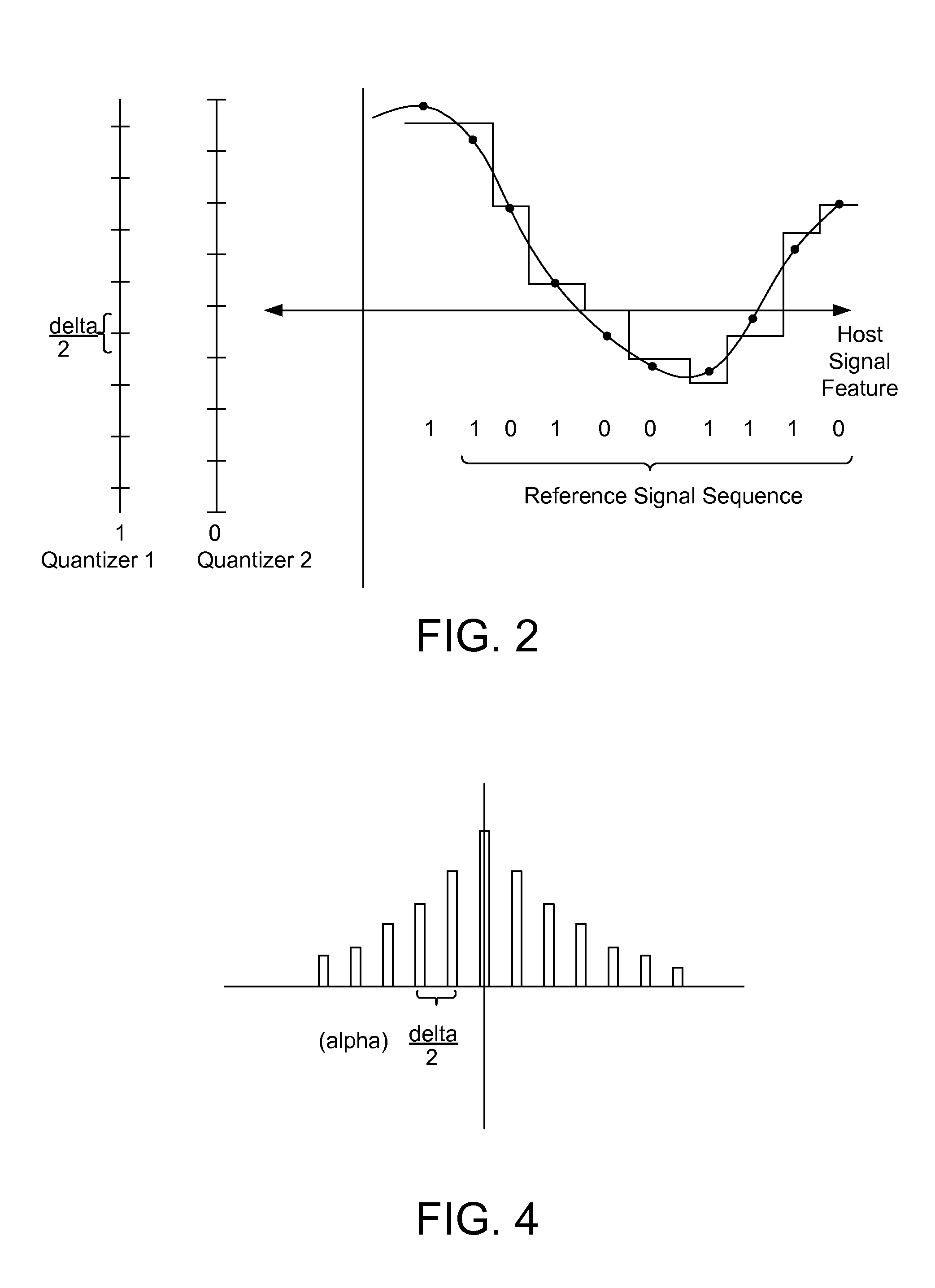
[0009]To read embedded data, the samples of content expected to include auxiliary data are evaluated to determine which quantizer or quantization bin they represent. Symbol errors may result when samples get mapped to a different quantizer or quantization bin relative to the one used to encode them. Error correction encoding tends to mitigate symbol errors if the distortion is not significant or does not impact the embedded data adversely.
[0010]Quantization embedding techniques may be performed on samples or other signal features in various signal or transform domains of multimedia signals. To reduce the impact of distortion, the embedding domain may be chosen such that samples in that domain are relatively robust or invariant to expected types of distortion.
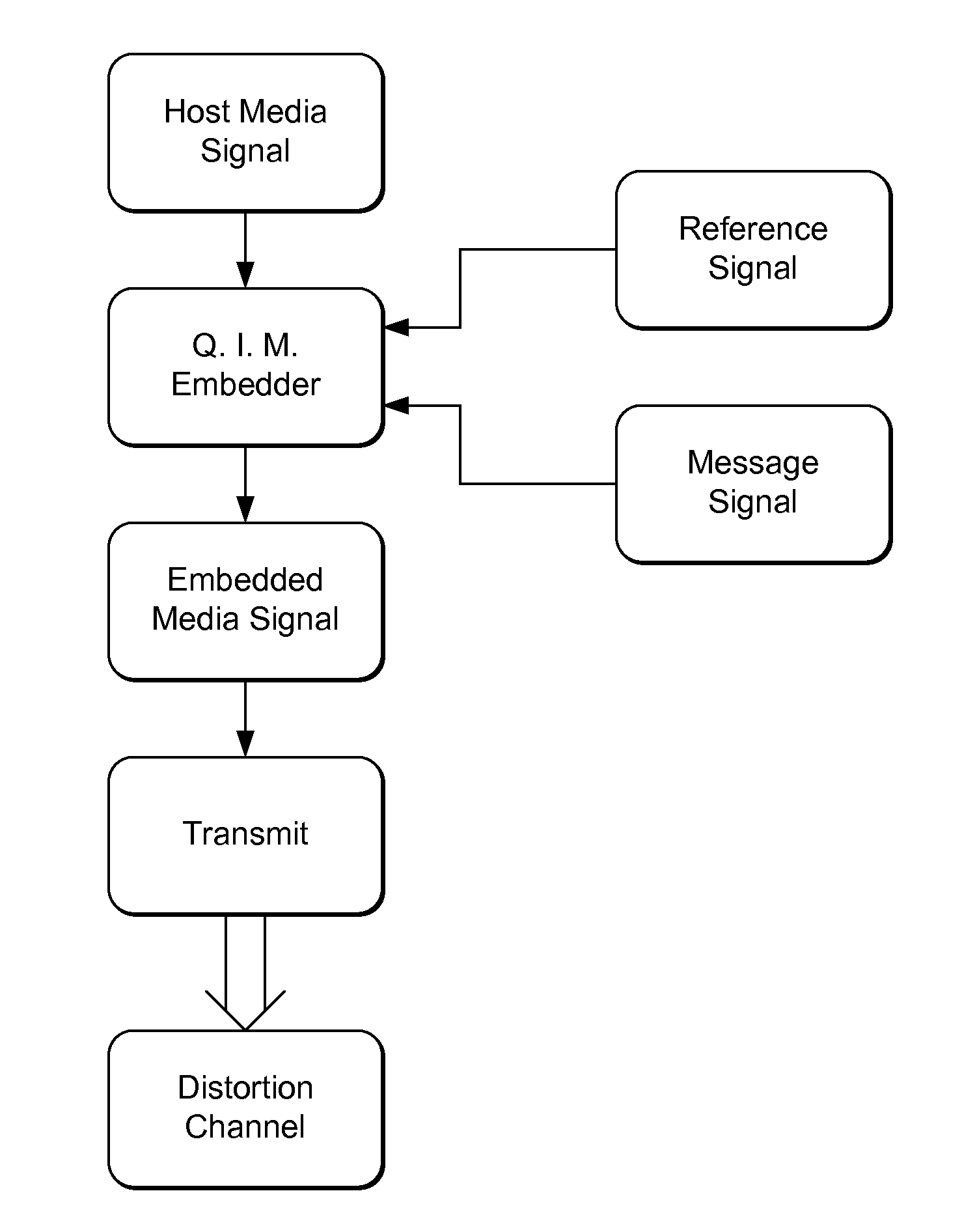
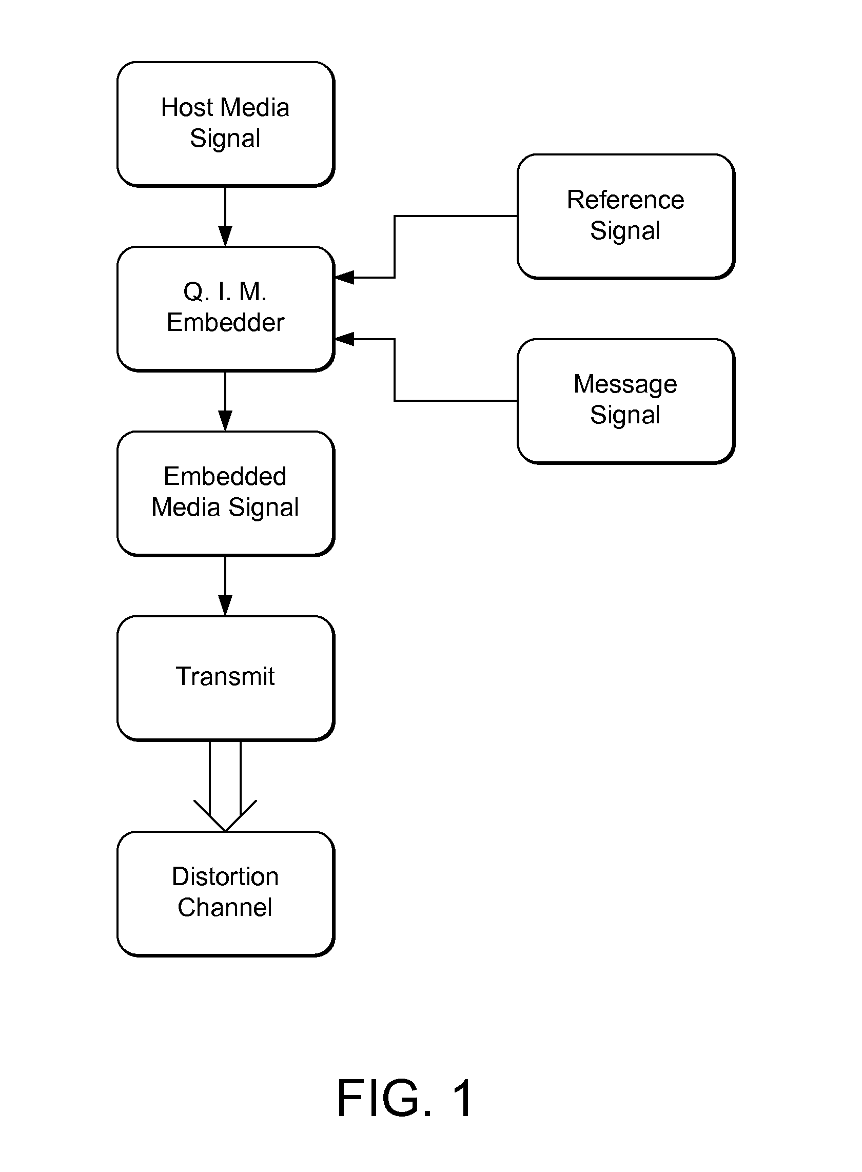
[0012]This document details methods of synchronizing embedded data readers in quantization embedding systems for multimedia content. In the embedder, a reference signal and message symbols are encoded using a quantization embedding method. In the reader, the distorted data samples are evaluated to derive quantizers or quantization bins. The reader then uses the derived quantization information to convert the distorted data to raw symbol estimates. These raw symbol estimates are then evaluated to detect the presence of the reference signal. Once detected, the reference signal is used to determine the distortion and compensate for it by adjusting the quantization information or distorted data such that message symbols may be decoded more accurately.
[0013]Certain forms of offset and gain distortion make it difficult to recover hidden data embedded in an audio or image signal by quantization techniques. To compensate for this offset and gain distortion, an embedded data reader analyzes a statistical distribution (e.g., a histogram) of feature samples in an audio or image signal suspected of having hidden auxiliary data to derive an estimate of quantizers used to encode a reference signal (deriving an estimate of the quantizers is equivalent to estimating the offset and gain distortions). The estimated quantizers then recover the reference signal, and the reader uses the reference signal to determine and compensate for geometric or temporal distortion, like spatial scaling and rotation of image data, and time scale and speed changes of audio data. After compensating for such distortion, the reader can then more accurately recover hidden message data using quantization techniques to extract the message. The reference signal is preferably repeated in blocks of the image or audio data to enable synchronization at many points in an image or audio data stream.

Problems solved by technology

Symbol errors may result when samples get mapped to a different quantizer or quantization bin relative to the one used to encode them.
A challenge associated with data hiding methods, including quantization embedding techniques, is synchronizing the reader with the embedded data after the host signal carrying the embedded data has been distorted, e.g., geometrically or temporally distorted.
Such forms of distortion have the effect of distorting the quantization bins.
Thus, if the same quantizers or bins are used to interpret embedded data symbols in the reader as in the embedder, the reader may map distorted samples to the wrong quantizer or bin.
Certain forms of offset and gain distortion make it difficult to recover hidden data embedded in an audio or image signal by quantization techniques.

Method used


Image

  • Quantization-Based Data Embedding in Mapped Data
  • Quantization-Based Data Embedding in Mapped Data
  • Quantization-Based Data Embedding in Mapped Data

Examples


example implementation

CDF Calculation

[0210]The CDF is calculated using all available reference locations in each block that is currently being embedded. The reference locations are controlled by a location key. One quarter of the total number of available locations within a block are reference locations; and these locations are chosen pseudo-randomly when the key is created. The CDF is generated from the histogram of the reference locations within the block according to equation 1. The histogram bins range from 0 to 255 in steps of one.

Quantizer Configuration

[0211]The first quantizer centroid is the nearest position in luminance to the last point where F(x) is equal to zero. The remaining centroids are assigned according to the finite state machine procedure described previously. We configure the quantizers using two different choices for the parameter that controlled the target separation in luminance. When increasing the target spacing we fix the embedding distortion and increase the distortion compens...


PUM


Abstract

Novel methods and systems for quantization based data embedding and reading in host signals, such as image, audio and video signals. To embed auxiliary data in a host signal, an embedder maps the host signal from a first domain into a mapped signal in a second domain. The embedder performs quantization based embedding of auxiliary data into the host signal using quantizers. The quantizers are adapted such that the relationship between corresponding quantizers in the first and second domains satisfies a predetermined constraint. The mapping improves the robustness of the data embedding method by increasing the chances that the embedded data can be recovered by an auxiliary data reader after modifications. A related embedding method projects the mapped signal unto a vector, and specifically, a pseudorandom vector. It performs quantization based embedding on the projected signal. The use of this projection provides added robustness of the embedded data to noise and other forms of distortion.

Description

RELATED APPLICATION DATA[0001]This patent application is a continuation of U.S. application Ser. No. 12 / 124,032, filed May 20, 2008 (now U.S. Pat. No. 7,769,202) which is a continuation of U.S. application Ser. No. 10 / 742,637, filed Dec. 19, 2003 (now U.S. Pat. No. 7,376,242) which is a continuation in part of U.S. application Ser. No. 10 / 469,474, filed Jun. 14, 2004 (now U.S. Pat. No. 7,454,033), which is the U.S. Nationalization of PCT Application No. PCT / US02 / 08844 (published as WO02 / 078234), filed Mar. 22, 2002. PCT Application No. PCT / US02 / 08844 claims priority to U.S. patent application Ser. No. 09 / 895,867, filed Jun. 28, 2001 (now U.S. Pat. No. 6,483,927), which claims priority to U.S. Provisional Application 60 / 278,049, filed Mar. 22, 2001, which are herein incorporated by reference.[0002]Application Ser. No. 10 / 742,637 also claims priority to U.S. Provisional Applications 60 / 435,401, filed Dec. 19, 2002, and 60 / 480,990, filed Jun. 23, 2003, which are hereby incorporated by ...

Claims


Application Information

Patent Timeline
Patent Type & Authority Applications(United States)
IPC IPC(8): H04K1/00G06K9/00
CPCG06T1/0064G06T2201/0061G06T2201/0601H04N1/3232G10L19/032H04N1/32187H04N1/32197G10L19/018
Inventor BRADLEY, BRETT ALANSTACH, JOHN
Owner DIGIMARC CORP
Learn More