Access channel structure for wireless communication system

Inactive Publication Date: 2005-06-07
IPR LICENSING INC
View PDF8 Cites 35 Cited by
  • Summary
  • Abstract
  • Description
  • Claims
  • Application Information

AI Technical Summary

Benefits of technology

[0017]The additional pilot symbols embedded in the payload portion are preferably used in a cross product modulator to further undo the effects of

Problems solved by technology

Because PN codes in and of themselves do not provide perfect separation of the channels, certain systems have added an additional layer of coding, and/or use modified PN codes.
If they do not, interference between the individual signal

Method used


Image

  • Access channel structure for wireless communication system
  • Access channel structure for wireless communication system
  • Access channel structure for wireless communication system

Examples


Example

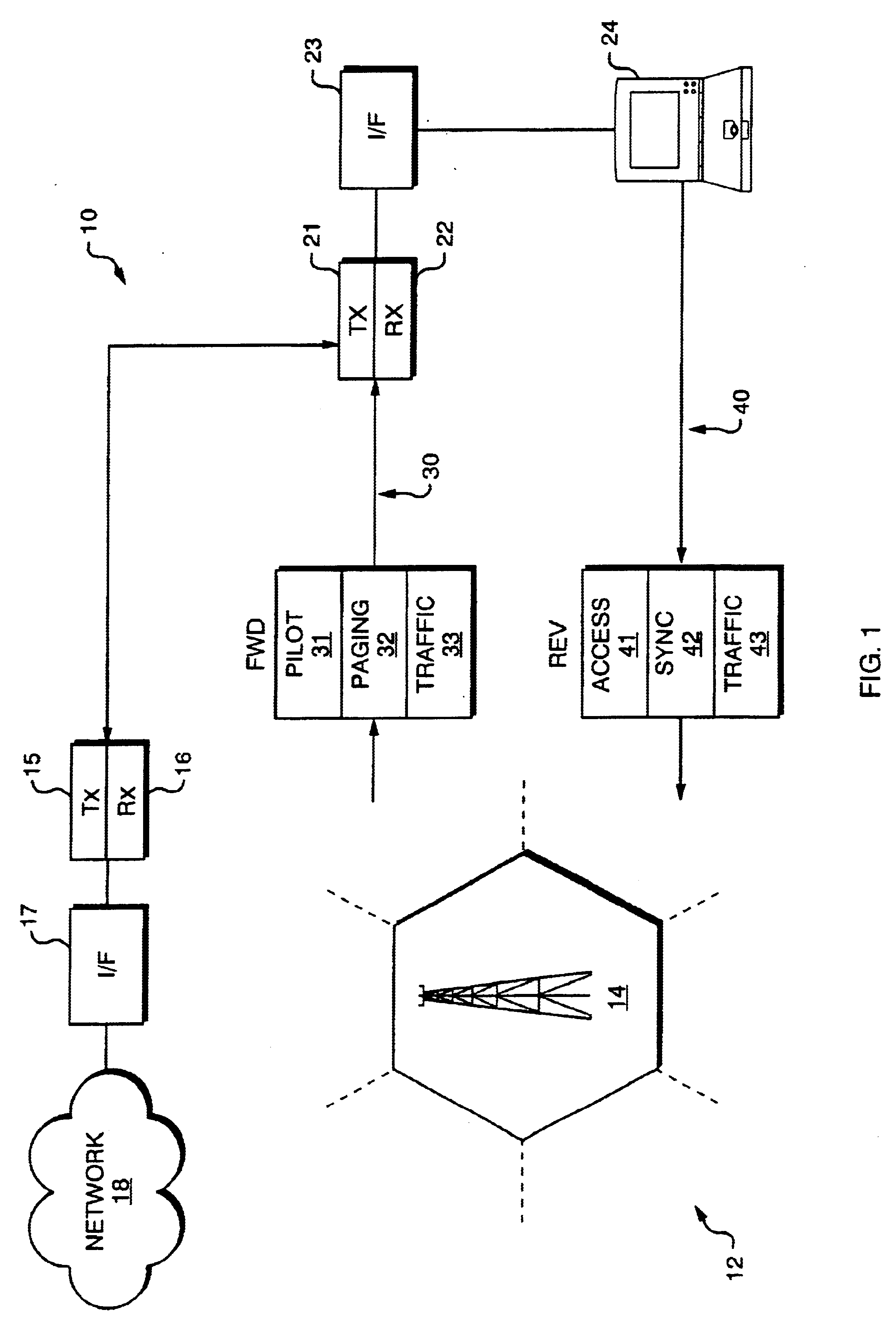
[0026]Turning attention to the drawings, FIG. 1 is a generalized diagram showing a wireless data communication system 10 that makes use of an access channel having embedded pilot symbols in order to effectuate coherent demodulation. The system 10 consists of a base station 12 and a field unit 20. The base station 12 is typically associated with a predetermined geographic region 14 in which wireless communication service is to be provided.

[0027]The base station 12 contains several components, including a radio transmitter 15, receiver 16, and interface 17. The interface 17 provides a data gateway between the base station 12 and a data network 18 such as the Internet, a private network, a telephone network, or other data network.

[0028]The field unit 20 consists of a corresponding receiver 21, transmitter 22, and interface 23. The interface 23 permits the field unit 20 to provide data signals to and receive data signals from computing equipment 24 such as a laptop computer, Personal Di...


PUM


Abstract

A technique for efficient implementation of pilot signals on a reverse link in a wireless communication system. An access channel is defined for the reverse link such that within each frame, or epoch, a portion is dedicated to sending only pilot symbols. Another portion of the frame is reserved for sending mostly data symbols; however, within this second portion of the frame, additional pilot symbols are interleaved among the data symbols. The pilot symbol or preamble portion of the access channel frame allows for efficient acquisition of the access signal at the base station, while providing a timing reference for determining the effects of multipath fading. In particular, a pilot correlation filter provides a phase estimate from the pilot symbols in the preamble portion, which is then used to decode the data symbols in the payload portion. An access acquisition portion of the receiver uses the phase estimates provided by the pilot correlation filter to process the output of a data symbol correlation filter. The additional pilot symbols embedded in the payload portion are used in a cross product operation to further resolve the effects of multipath fading.

Description

RELATED APPLICATION[0001]This application claims the benefit of U.S. Provisional application Ser. No. 60 / 181,071, filed on Feb. 8, 2000, entitled “Access Channel Structure For Wireless Communication System”. The entire teachings of the above application is incorporated herein by reference.BACKGROUND OF THE INVENTION[0002]The present invention relates generally to the field of wireless digital communications and more particularly to a technique for encoding access channel signals.[0003]The increasing use of wireless telephones and personal computers has lead to a corresponding demand for advanced wireless communication services which were once thought only to be meant for use in specialized applications. In particular, wireless voice communication first became widely available at low cost through the cellular telephone network. The same has also become true for distributed computer networks, whereby low cost, high speed access to data networks is now available to the public through I...

Claims


Application Information

Patent Timeline
IPC IPC(8): H04B1/707H04L7/04H04B1/7115H04B1/7075H04W28/18
CPCH04B1/707H04L7/041H04B2201/70701H04B1/7075H04B1/7115H04L5/0046
Inventor HOFFMANN, JOHN E.NELSON, JR., GEORGE RODNEYPROCTOR, JR., JAMES A.ROUPHAEL, ANTOINE J.
Owner IPR LICENSING INC
Why Eureka
Try Eureka