Leg assembly

Active Publication Date: 2009-03-26
PELICAN PROD INC
View PDF4 Cites 47 Cited by
  • Summary
  • Abstract
  • Description
  • Claims
  • Application Information

AI Technical Summary

Benefits of technology

[0010]It is an object of the present invention to provide a lightweight leg assembly for a storage case.
[0011]It is a further object of the present invention to provide a leg assembly for a storage case that can be used to securely and stably support a lid of the case to that the case may be used as a support structure such as a table.
[0012]It is yet another object of the present invention to provide a lightweight leg assembly for a storage case that can be used to securely and stably support a lid of the storage case to that the case may be used as a support structure through the use of an active bracketing system and cross-braces.
[0014]It is a further object of the present invention to provide a leg assembly for a storage case that allows for unobstructed access to an interior cavity of a base of the storage case.

Problems solved by technology

Such cases are relatively unstable, however, as the legs are secured through a passive bracketing system.
Tolerance increases can, in turn, result in lateral movement of the lid relative to the base and instability of the support structure.
Additionally, known cases do not include any ancillary structural supports, such as cross members, that bridge and stabilize the legs and help support the weight of the relatively heavy metal lid.
This lack of supplemental support further adds to the instability of the legs and impairs the efficacy of such cases in the field.
Moreover, the legs of known cases do not allow attachment of lids with varying depths.
The legs of these cases are also quite wide and spaced in a configuration that does not allow for easy access to an interior cavity of the base.
Given the width of the legs, access to the interior cavity of the base is partially obstructed.
This can be problematic if the cases are deployed for field use by military medical personnel who need to quickly locate and extract equipment.

Method used


Image

  • Leg assembly
  • Leg assembly
  • Leg assembly

Examples


Embodiment Construction

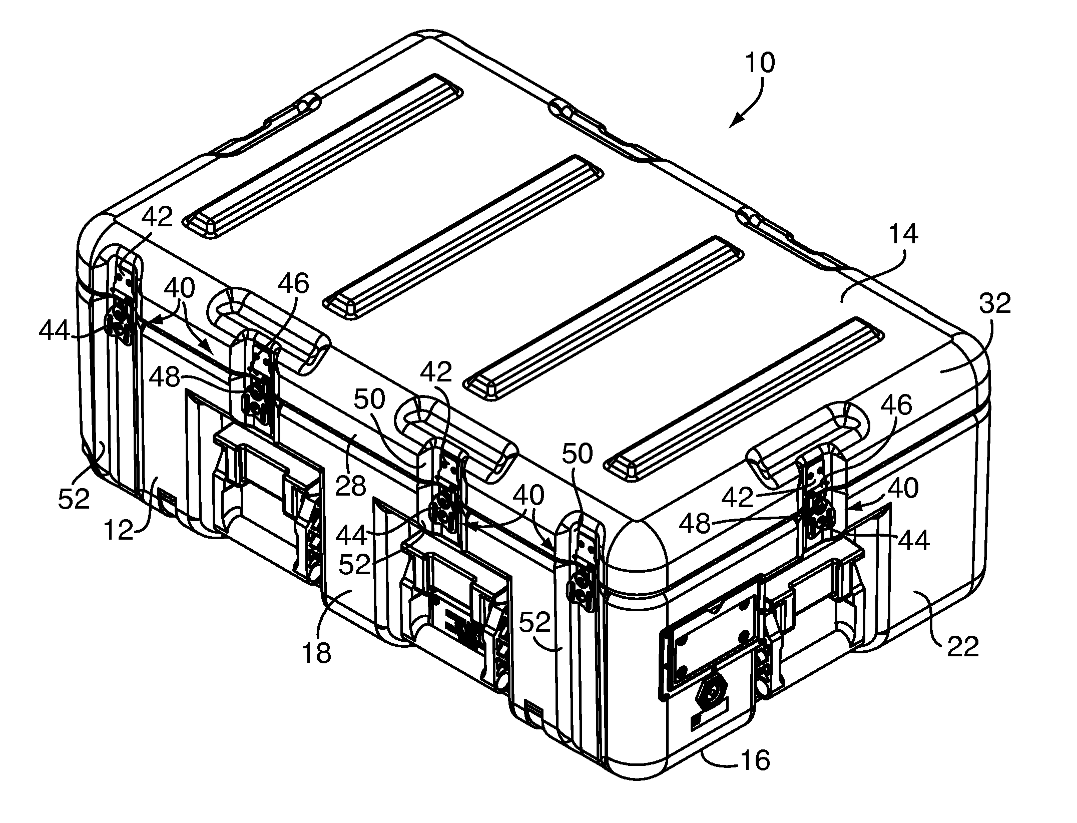
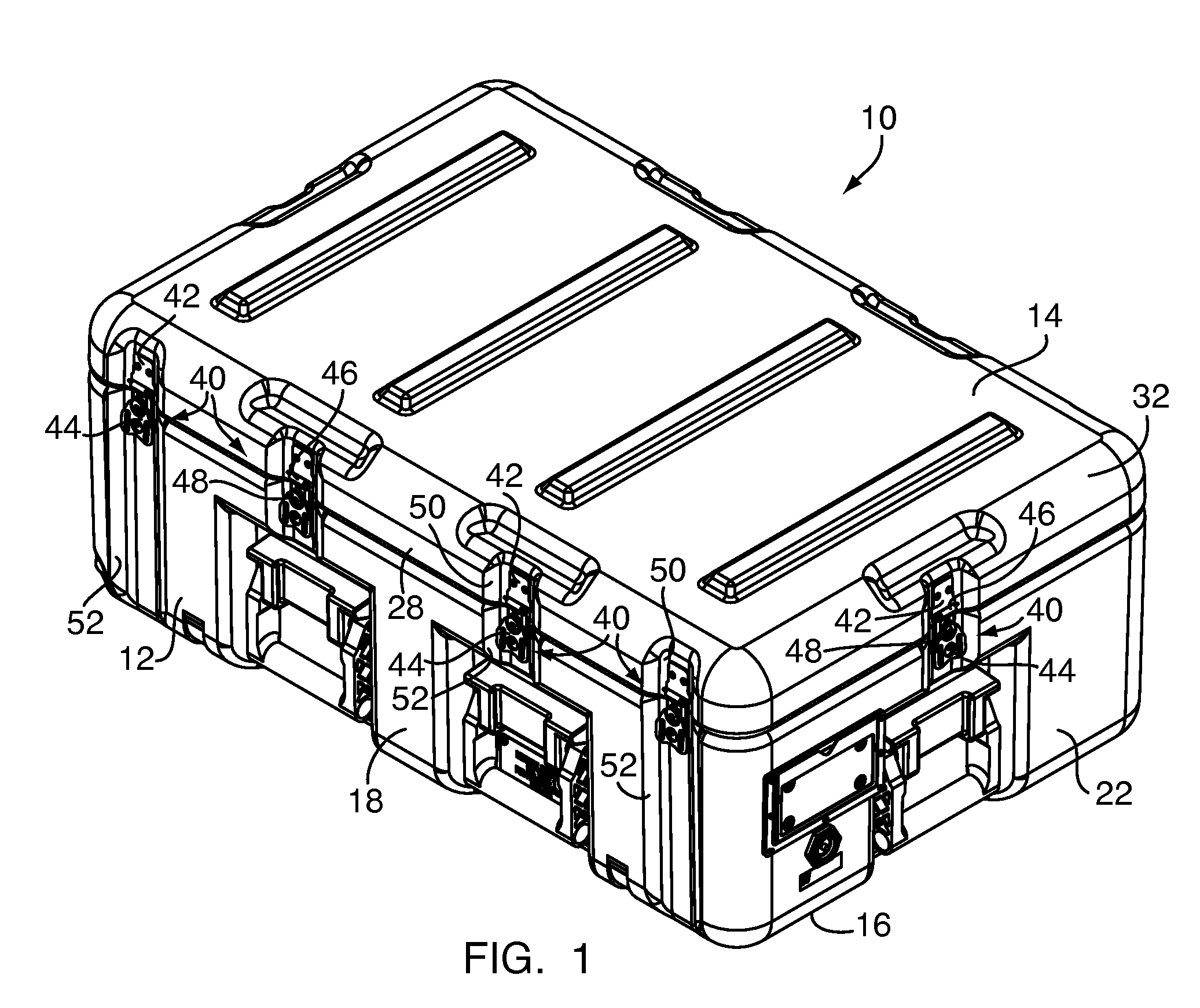
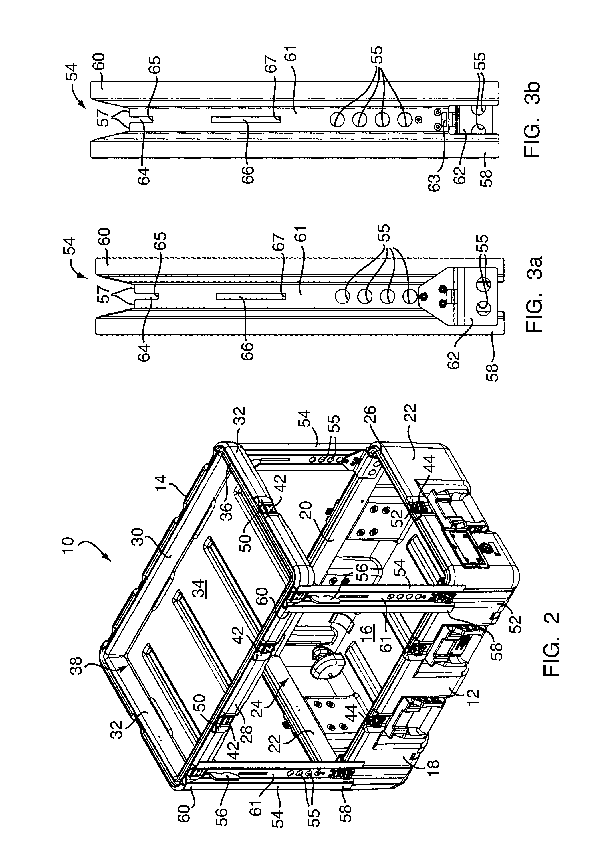
[0025]FIGS. 1 and 2 show a perspective view of a preferred embodiment of a storage case 10 and leg assembly according to the present invention. The case 10 includes a bottom portion or base 12 and a top portion or lid 14. The base 12 has a horizontal bottom panel 16 and four vertical panels or walls, which include a front wall 18, a rear wall 20, and two sidewalls 22. The vertical walls form an inner cavity 24. The base 12 also has a parting line edge 26 member around the periphery of the vertical walls. The term “parting line” refers to the portion of a case where the base and lid meet. Similarly, the lid includes four vertical panels or walls, i.e., a front wall 28, a rear wall 30, and two sidewalls 32. The lid 14 includes a horizontal bottom panel 34 and peripheral parting line edge member 36, which aligns with the parting line member 26 of the base 12 when the case 10 is closed. The bottom panel 34 and vertical panels of the lid 14 form an inner cavity 38.

[0026]The case is secur...


PUM


Abstract

A leg assembly for selective attachment to a portable support structure having a base and removable lid said leg assembly. The leg assembly includes a plurality of legs that are selectively attachable to both the base and lid. When attached, the legs extending from the base to the lid thereby supporting the lid. The legs are substantially parallel to one another. The assembly further includes at least one cross member extending between two of the legs to stabilize and prevent lateral movement of the legs. The cross member also abutingly contacts and supports the lid so that the base and lid may function as a support structure.

Description

FIELD OF THE INVENTION[0001]This invention relates generally to a leg assembly, and more particularly to a leg assembly that may be removably secured to a storage case to provide a stable and lightweight base so that the case may be optionally used as a support structure such as a table.BACKGROUND OF THE INVENTION[0002]Known storage cases may be selectively converted for use as a support structure such as a table. One such case has been used in military applications and in particular as a chest to store equipment for use by medical personnel. The case is manufactured from metal and includes four relatively wide metal legs that attach to both a base portion of the case and a lid portion, which forms a support surface. These cases are typically rectangular and include front, back and sidewalls. When configured as a table, the base portion has an open interior cavity that can be accessed by reaching between the legs.[0003]Such cases are relatively unstable, however, as the legs are sec...

Claims


Application Information

Patent Timeline
IPC IPC(8): B65D61/00
CPCF16B12/44A45C5/04A47B3/10A47B13/00B25H1/04B25H3/02A45C9/00Y10T403/70E05B17/0025A45C7/00E05C19/105E05C19/10B65D25/24
Inventor PATSTONE, CHRISTOPHER H.
Owner PELICAN PROD INC
Why Eureka
Try Eureka