

Hydrogen Fuel Feeding System and Fuel Cell System
- Summary
- Abstract
- Description
- Claims
- Application Information
AI Technical Summary
Benefits of technology
Problems solved by technology
Method used
Image

Examples
first embodiment
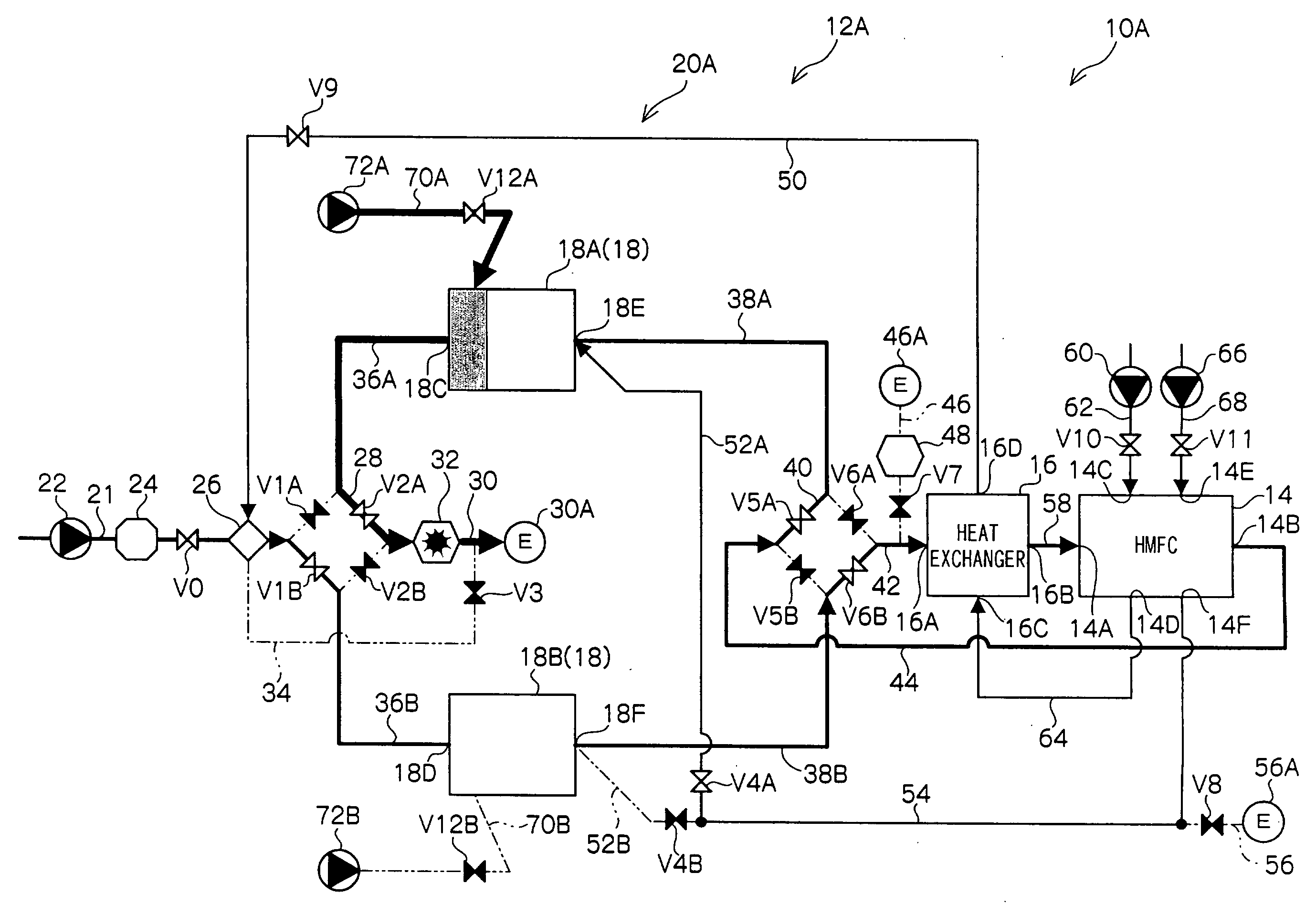
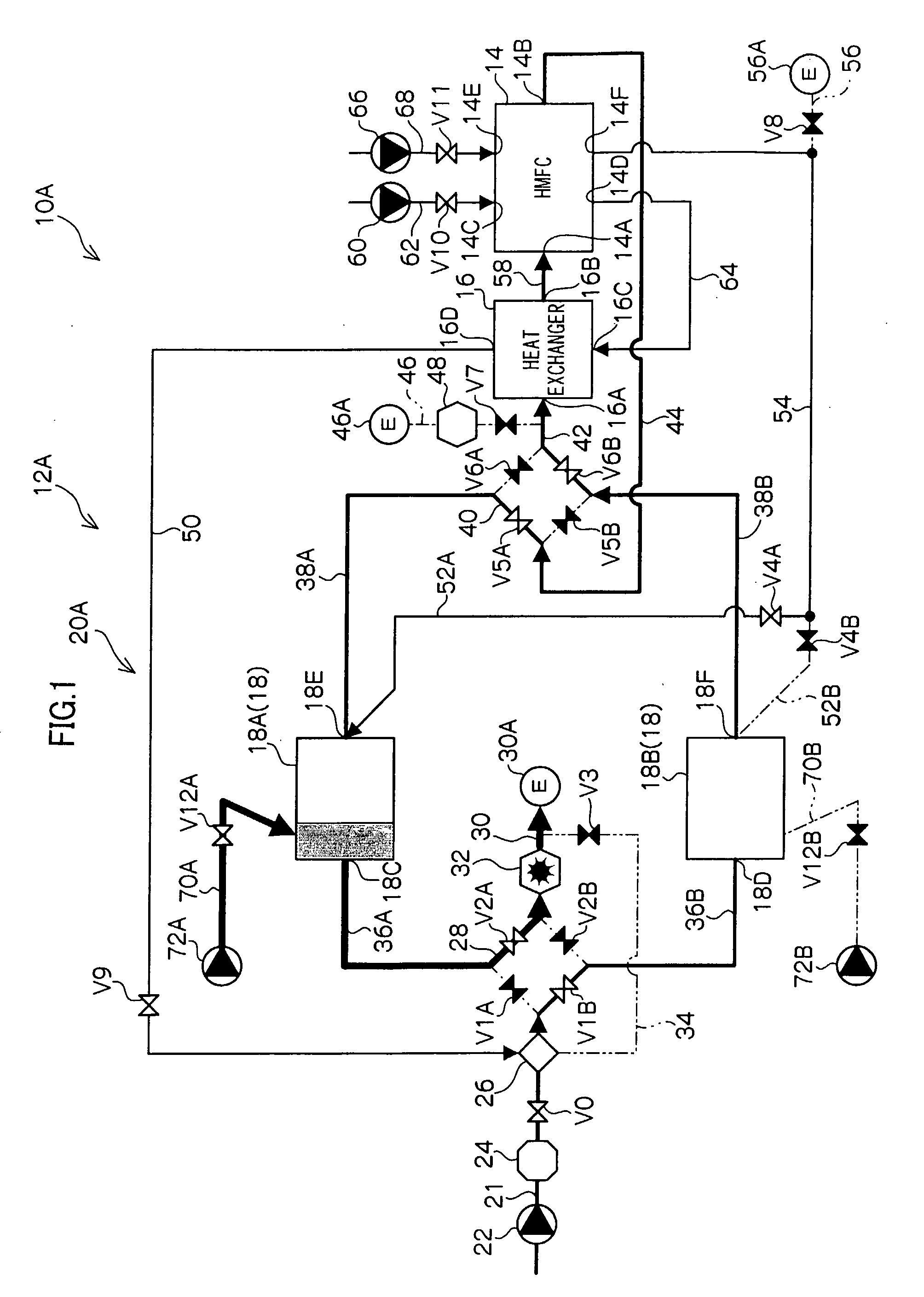
[0068]FIG. 1 illustrates the fuel cell systems 10A according to the first embodiment of the present invention. FIG. 1 illustrates the status at which the reactor 18A is switched from the reforming process into the regeneration process.
[0069]As shown in this FIG. 1, the fuel cell system 10A is provided with a hydrogen fuel feeding system 12A, and the hydrogen fuel feeding system 12A has a switching device 20A that is provided, in addition to the configuration of the switching device 20, with auxiliary air feeding lines 70A and 70B for introducing air from the cylinder shaped tubular wall portion of each reactor 18. One end of the auxiliary air feeding lines 70A and 70B is connected to the exhaust parts of respective air pumps 72A and 72B. Thereby, the switching device 20A is configured so as to be capable of directly introducing air into the reactors 18, without passing through the first line 36A, the second line 36B, the third line 38A, the fourth line 38B, and the combustion air fe...
second embodiment
[0076]FIG. 7 illustrates a fuel cell system 10B according to the second embodiment of the present invention. FIG. 7 shows the status at which the reactor 18A is switched from the reforming process to the regeneration process in the fuel cell system 10B.
[0077]As shown in FIG. 7, the fuel cell system 10B is provided with a hydrogen fuel feeding system 12B. The hydrogen fuel feeding system 12B is common to the hydrogen fuel feeding system 12A according to the first embodiment in that the hydrogen fuel feeding system 12B is provided with the auxiliary air feeding lines 70A and 70B, the air pumps 72A and 72B, and the valves V12A and V12B. A switching device 20B of this hydrogen fuel feeding system 12B is different from the first embodiment combusting residual reforming gas in the external exhaust air processor 32 in that the switching device 20B performs all of the oxidation processing (combusting in this embodiment) of the residual reforming gas within the first reactor 18A.
[0078]Specif...
fourth embodiment
[0091]FIG. 9 illustrates a fuel cell system 10D according to the fourth embodiment. Further, FIG. 9 shows the status at which the reactor 18A is switched from the reforming process into the regeneration process in the fuel cell system 10D.
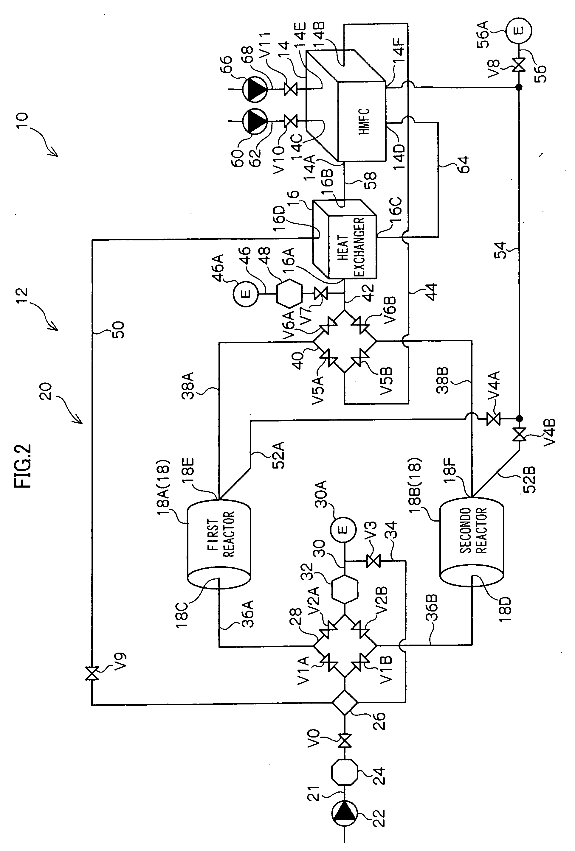
[0092]As shown in FIG. 8, the mechanical configuration of the fuel cell system 10D is entirely the same as the basic configuration of the fuel cell system 10. In other words, in the fuel cell system 10D, the mechanical configuration of a switching device 20D in a hydrogen fuel feeding system 12D is the same as that of the switching device 20 and the switching device 20D is characterized by the switching control of a control apparatus 90D from the reforming process to the regeneration process of the reactor 18. Specifically, in the fuel cell system 10D, the control apparatus 90D is configured so as to stop the feeding of the hydrocarbon reactant to the hydrogen fuel feeding system 12 by closing the valve V0 (stopping the fuel pump 22) before the fir...
PUM
 Abstract
Description
Claims
Application Information