
Subtalar implant and kit

Inactive Publication Date: 2009-04-16
WRIGHT MEDICAL TECH
View PDF14 Cites 23 Cited by
  • Summary
  • Abstract
  • Description
  • Claims
  • Application Information

AI Technical Summary

Benefits of technology

[0009]In another embodiment, the present invention provides a kit useful in certain surgical procedures such as correcting podiatric disorders as, for example, using subtalar implants. The kit of the present invention can comprise a tray having a plurality of first and second receiving formations. Selectively received in each of the first receiving formations are respective ones of a series of sizing tools. Selectively received in each of the second receiving formatio

Problems solved by technology

Generally speaking modern implants are either cylindrical or conical in shape, the cylindrically shaped implants generally providing a less desirable anatomical fit than the conically shaped implants.

Method used


Image

  • Subtalar implant and kit
  • Subtalar implant and kit
  • Subtalar implant and kit

Examples


Embodiment Construction

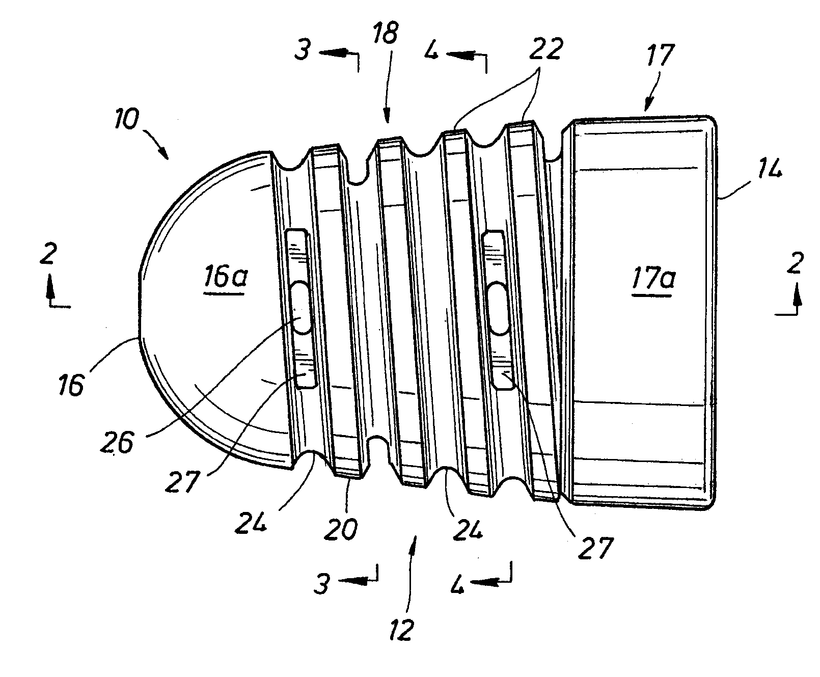
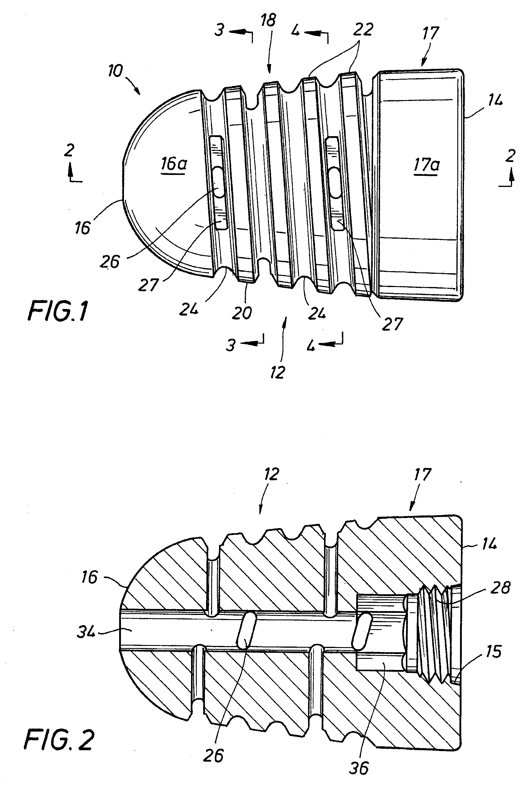
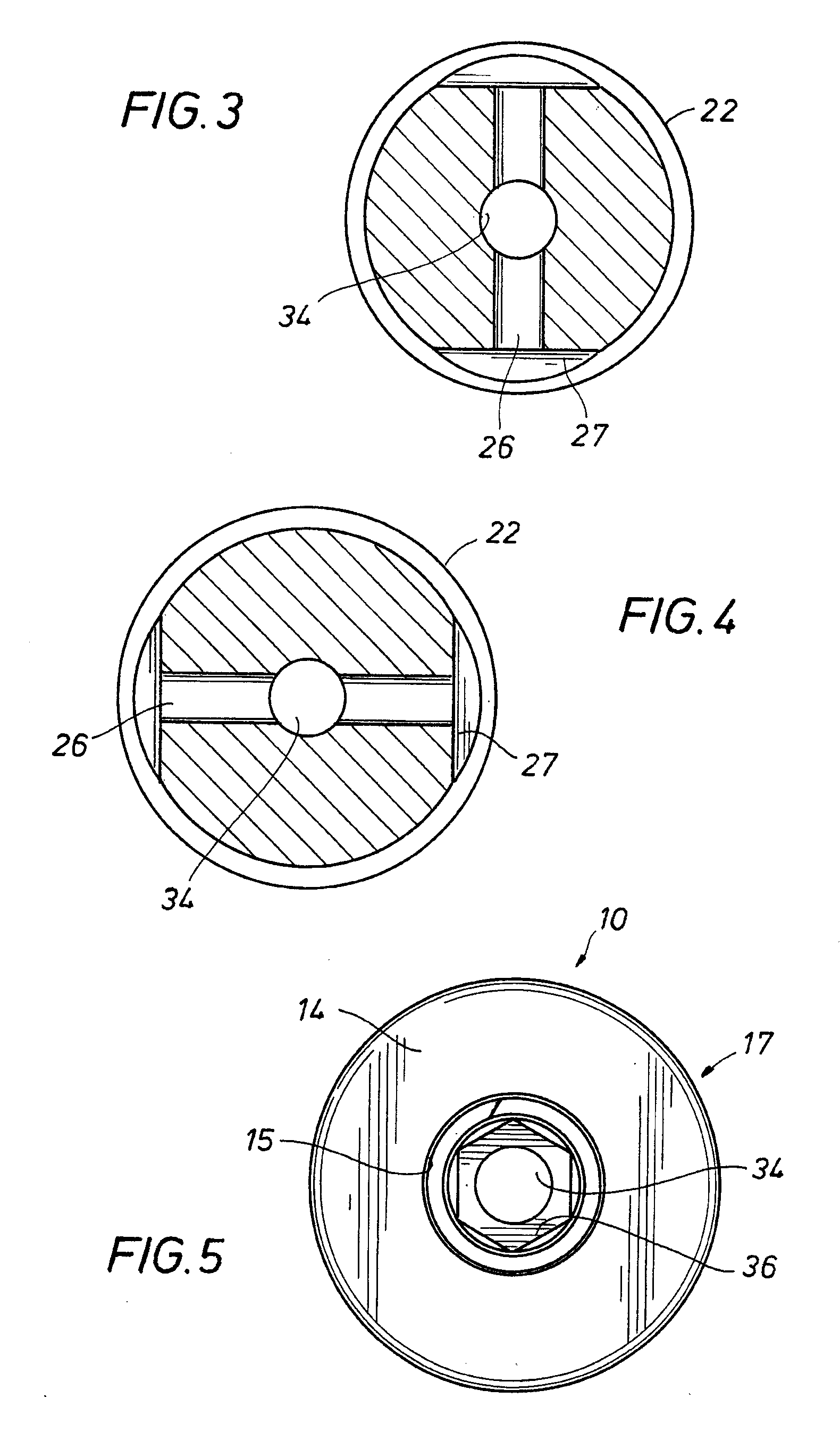
[0019]Referring first to FIG. 1, the implant, shown generally as 10, includes an elongate body 12 having a proximal end with a planar face 14 and a distal end 16 having a domed shape. As can be seen from FIG. 1, body 12 has a cylindrical portion 17 having a cylindrical surface 17a proximate the planar face 14 of the proximal end and a conical portion 18, conical portion 18 extending axially from the cylindrical portion 17 toward the domed shape portion 16a on the distal end 16 and being provided with tapered male threads 20 having frustoconical crests 22 and radiused roots 24. As can be seen with reference to FIGS. 1 and 2, apertures 26 are formed in grooves 27 in the roots 24 and extend through the body 12 and are in open communication with a bore 34 which extends from and through proximal end 14 to and through distal end 16. Grooves 27 and apertures 26 provide receptacles for post implantation osseous tissue growth to further stabilize the implant 10.

[0020]Bore 34 has a small, cha...


PUM


Abstract

A subtalar implant comprising a body with a proximal end and a distal end, the body including a cylindrical portion proximate the proximal end, an externally threaded frustoconical portion extending generally from the cylindrical portion toward the distal end, an axially extending bore through the proximal end and the distal end, a driver formation coaxial with the bore and a female threaded portion coaxial with the bore and extending from about the proximal end toward the driver formation, the threads on the externally threaded portion being of an opposite turn to the threads on the male threaded portion.

Description

CROSS REFERENCE TO RELATED APPLICATION[0001]This application claims the priority of U.S. Provisional Application No. 60 / 999,094 filed on Oct. 16, 2007, the disclosure of which is incorporated herein by reference for all purposes.BACKGROUND OF THE INVENTION[0002]1. Field of the Invention[0003]The present invention relates to a surgical implant more specifically a subtalar implant to correct podiatric disorders and a bit useful in performing surgical procedure.[0004]2. Description of Prior Art[0005]Subtalar implants for correcting podiatric disorders including flat foot dates back to the 1940's. Originally, to treat flat foot a bone graft or silicone wedge was used to elevate the sinus tarsi and to limit pronation of the subtalar joint. These techniques gave way to the use of a stemmed polyethylene block. All of the above methods were later replaced with modern, threaded implants for surgical implantation within the sinus tarsi. This is exemplified, for example, in U.S. Pat. No. 6,168...

Claims


Application Information

Patent Timeline
IPC IPC(8): A61B17/56A61F2/42
CPCA61B17/562A61B17/8875A61F2002/4223A61B17/92A61B2019/444A61B17/8888A61B90/92
Inventor FORRESTER, PERRY C.
Owner WRIGHT MEDICAL TECH
Features
  • Generate Ideas
  • Intellectual Property
  • Life Sciences
  • Materials
  • Tech Scout
  • Unparalleled Data Quality
  • Higher Quality Content
  • 60% Fewer Hallucinations
Learn More