Modular backup fluid supply system

a hydraulic fluid supply system and module technology, applied in the direction of thin material handling, underwater drilling, borehole/well accessories, etc., can solve the problems of affecting the operation of subsea drilling, affecting the production of wells, and affecting the safety of drilling equipment, so as to achieve safe and efficient bypass of faulty components and efficient redundancy

Inactive Publication Date: 2009-04-23
TRANSOCEAN OFFSHORE DEEPWATER DRILLING
View PDF27 Cites 25 Cited by
  • Summary
  • Abstract
  • Description
  • Claims
  • Application Information

AI Technical Summary

Benefits of technology

[0008]In some embodiments, the present invention provides an improved method and apparatus to provide redundancy to fluid flow components via alternative flow routes. In some embodiments, the present invention allows for safe and efficient bypass of faulty components while allowing continued flow to functions or destinations. The present invention can be integrated into various existing flow systems or placed on entirely new flow systems to provide a layer of efficient redundancy. In other embodiments, the present invention relates to a stand alone control system for subsea blow out prevention (BOP) control functions. The present invention is particularly useful for hydraulically operated control systems and functions in water depths of 10,000 feet or more.
[0014]In some embodiments, a BOP hydraulic control system includes a blue central control pod, a yellow central control pod, and at least one modular valve block associated with each pod to provide universal backup for all control pod components. The modular valve blocks have an outlet that attaches to a hose via a temporary connection, and the other end of the hose attaches to any one of a number of intervention shuttle valves, each associated with a BOP function. Thus, each modular valve block provides redundancy for at least one BOP function.
[0015]In another embodiment, the invention comprises a stand alone subsea control system, modular in construction and providing retrievable, local, and independent control of a plurality of hydraulic components commonly employed on subsea BOP systems. Such a system eliminates the need for separate control pods. Other embodiments allow independent ROV intervention using an emergency hydraulic line routed from the surface to an ISV in the case of catastrophic system control failure of all BOP functions.
[0016]Independent and / or redundant control over BOP functions reduces downtime and increases safety. Furthermore, a control system having easily retrievable components allows fast and easy maintenance and replacement. The present invention, in some embodiments is compatible with a multitude of established systems and provides inexpensive redundancy for BOP system components. In another embodiment of the invention, control over the modular block valves is transparently integrated into an existing multiplex control system, allowing an operator to control the modular valve block using the existing control system.

Problems solved by technology

Subsea drilling operations may experience a blow out, which is an uncontrolled flow of formation fluids into the drilling well.
Blow outs are dangerous and costly.
Blow outs can cause loss of life, pollution, damage to drilling equipment, and loss of well production.
While the industry designed early versions of the pods to be retrievable in the event of component failure, later versions have increased in size and cannot be efficiently retrieved.
Further, while prior art systems have dual redundancy, this redundancy is often only safety redundancy but not operational redundancy, meaning that a single component failure will require stopping drilling operations, making the well safe, and replacing the failed component.
Stopping drilling to replace components often represents a major out of service period and significant revenue loss for drilling contractors and operators.

Method used


Image

  • Modular backup fluid supply system
  • Modular backup fluid supply system
  • Modular backup fluid supply system

Examples


Embodiment Construction

[0029]As used herein, the use of the word “a” or “an” when used in conjunction with the term “comprising” (or the synonymous “having”) in the claims and / or the specification may mean “one,” but it is also consistent with the meaning of “one or more,”“at least one,” and “one or more than one.” In addition, as used herein, the phrase “connected to” means joined to or placed into communication with, either directly or through intermediate components.

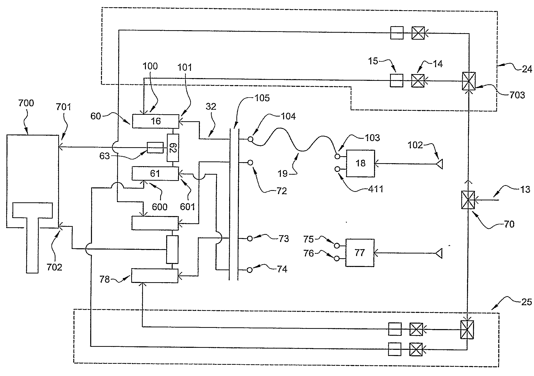
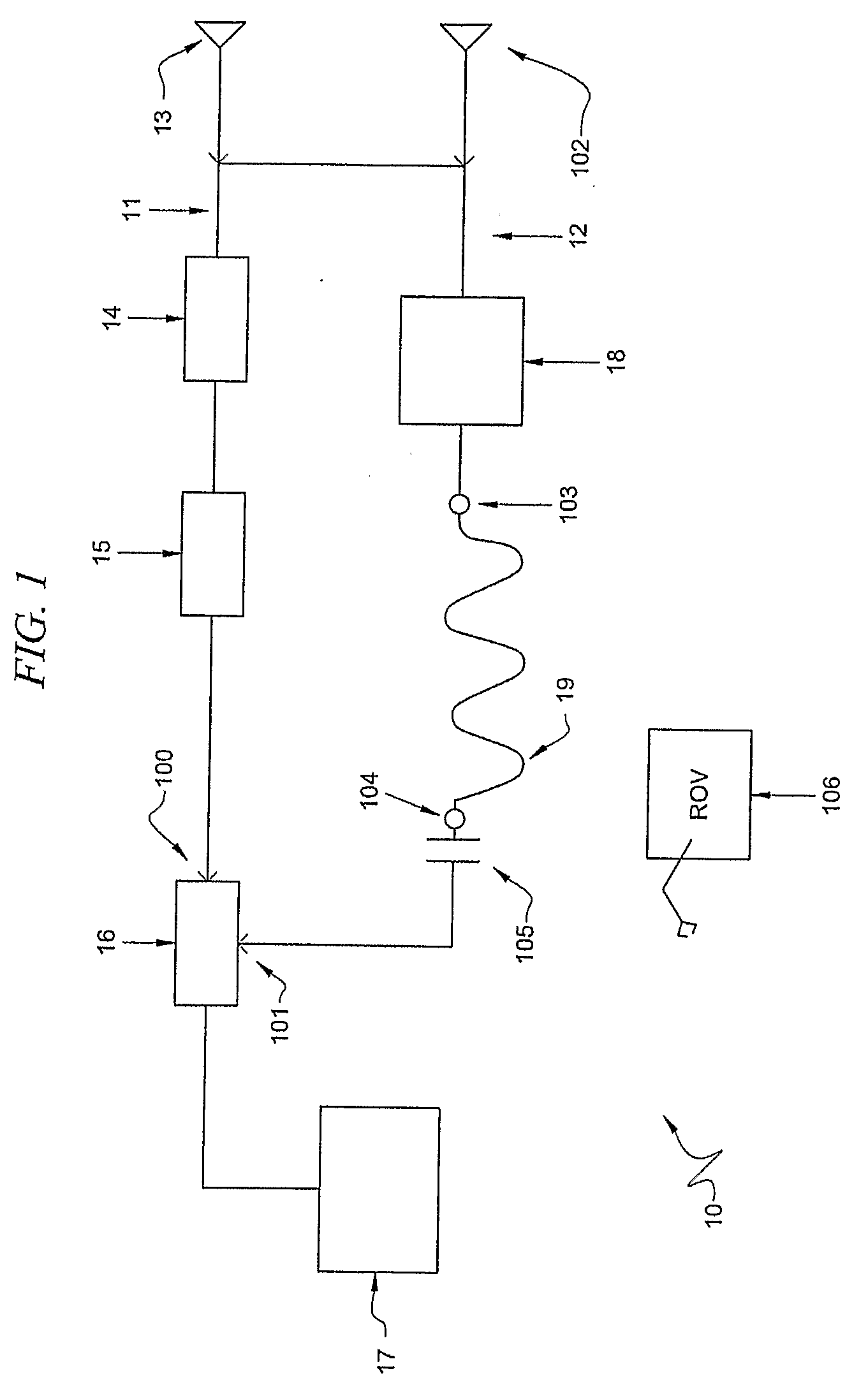
[0030]Referring to FIG. 1, one embodiment of the present invention comprises redundant fluid supply apparatus 10, comprising primary fluid flow route 11 and secondary fluid flow route 12. Primary fluid flow route 11 begins at fluid source 13 and continues through primary flow control components 14 and 15, through primary inlet 100 of intervention shuttle valve 16 and to destination 17. Secondary fluid flow route 12 begins at either fluid source 13 or alternate fluid source 102 and continues through modular valve block 18, through selectivel...


PUM


Abstract

A system and method to allow backup or alternate fluid flow routes around malfunctioning components using removable, modular component sets. In one exemplary embodiment, an ROV establishes a backup hydraulic flow to a BOP function by attaching one end of a hose to a modular valve block and the other end to an intervention shuttle valve, thus circumventing and isolating malfunctioning components. A compound intervention shuttle valve is provided that comprises first and second primary inlets, first and second secondary inlets, and an outlet. A modular valve block is provided that comprises a directional control valve, a pilot valve, a manifold pressure regulator, a pilot pressure regulator, stab type hydraulic connections and an electrical wet-make connection.

Description

CROSS-REFERENCE TO RELATED APPLICATIONS[0001]This application claims priority to provisional application No. 60 / 705,538.TECHNICAL FIELD[0002]The invention relates generally to a fluid supply system and apparatus and, more particularly, to a modular backup hydraulic fluid supply system and apparatus.BACKGROUND OF THE INVENTION[0003]Subsea drilling operations may experience a blow out, which is an uncontrolled flow of formation fluids into the drilling well. Blow outs are dangerous and costly. Blow outs can cause loss of life, pollution, damage to drilling equipment, and loss of well production. To prevent blowouts, blowout prevention (BOP) equipment is required. BOP equipment typically includes a series of functions capable of safely isolating and controlling the formation pressures and fluids at the drilling site. BOP functions include opening and closing hydraulically operated pipe rams, annular seals, shear rams designed to cut the pipe, a series of remote operated valves to allow...

Claims


Application Information

Patent Timeline
Patent Type & Authority Applications(United States)
IPC IPC(8): E21B33/064E21B33/00E21B33/038E21B34/06E21B33/035
CPCE21B33/0355Y10T137/87885
Inventor O'LEARY, STEVEDONOHUE, STEVETHRASH, TOM
Owner TRANSOCEAN OFFSHORE DEEPWATER DRILLING
Why Eureka
Try Eureka