System and method for providing additional blowout preventer control redundancy

a technology of supply system and control system, applied in the direction of sealing/packing, transportation and packaging, wellbore/well accessories, etc., can solve the problems of major out of service period, explosion of subsea drilling operations, pollution, etc., to achieve safe and efficient bypass of faulty components and efficient redundancy

Active Publication Date: 2013-02-19
TRANSOCEAN SEDCO FOREX VENTURES LTD
View PDF36 Cites 33 Cited by
  • Summary
  • Abstract
  • Description
  • Claims
  • Application Information

AI Technical Summary

Benefits of technology

[0009]The present invention provides an improved method and apparatus to provide redundancy to fluid flow components via alternative flow routes. The present invention allows for safe and efficient bypass of faulty components while allowing continued flow to and control of functions. The present invention can be integrated into various existing flow systems or placed on entirely new flow systems to provide a layer of efficient redundancy.
[0013]Independent and / or redundant control over BOP functions reduces downtime and increases safety. The present invention is compatible with a multitude of established systems and provides inexpensive redundancy for BOP system components. In another embodiment of the invention, control over the spare function is transparently integrated into an existing multiplex control system, allowing an operator to control the spare function using the existing control system.

Problems solved by technology

Subsea drilling operations may experience a blow out, which is an uncontrolled flow of formation fluids into the drilling well.
Blow outs are dangerous and costly, and can cause loss of life, pollution, damage to drilling equipment, and loss of well production.
While prior art systems have dual redundancy, this redundancy is effectively only safety redundancy but not operational redundancy, meaning that a single component failure will require stopping drilling operations, making the well safe, and replacing the failed component.
Stopping drilling to replace components often represents a major out of service period and significant revenue loss for drilling contractors and operators.
Further, when the BOP is at the surface, testing various functions typically requires breaking threaded connections to the BOP function.
Making and breaking threaded connections allows opportunity for damage to the connection, requiring replacement and possible downtime.

Method used


Image

  • System and method for providing additional blowout preventer control redundancy
  • System and method for providing additional blowout preventer control redundancy
  • System and method for providing additional blowout preventer control redundancy

Examples


Embodiment Construction

[0018]As used herein, the use of the word “a” or “an” when used in conjunction with the term “comprising” (or the synonymous “having”) in the claims and / or the specification may mean “one,” but it is also consistent with the meaning of “one or more,”“at least one,” and “one or more than one.” In addition, as used herein, the phrase “connected to” means joined to or placed into communication with, either directly or through intermediate components.

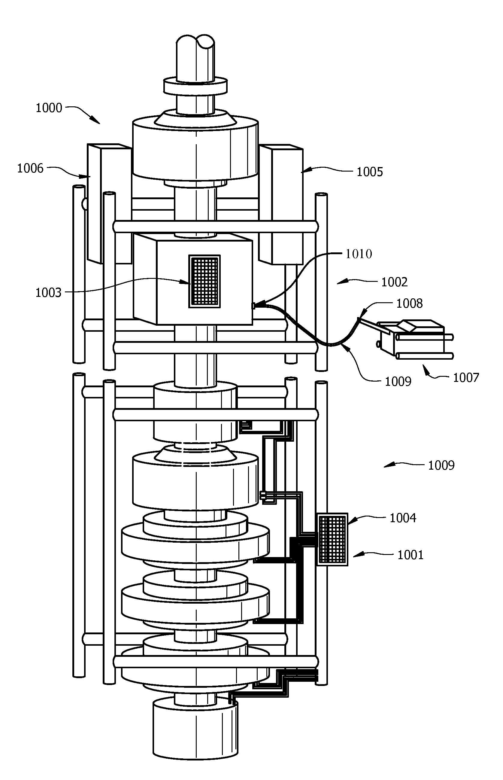
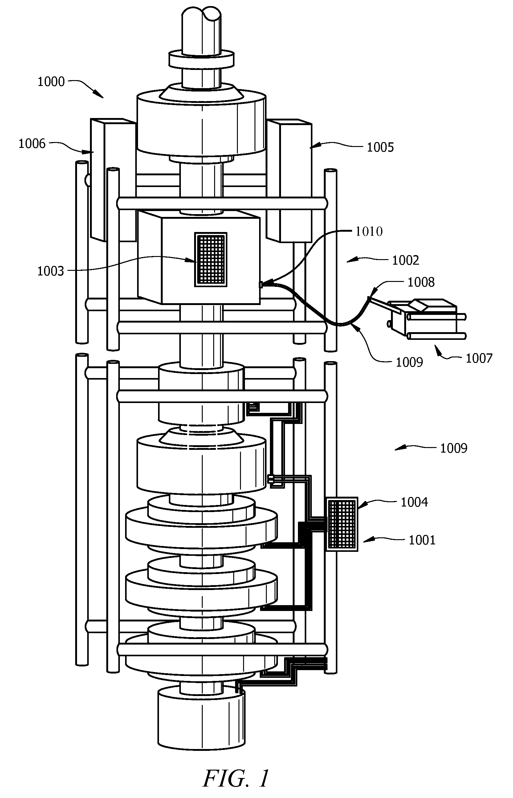
[0019]Referring to FIG. 1, one embodiment of the present invention comprises an apparatus providing operational redundancy. In the embodiment shown in FIG. 1, BOP system 1000 comprises BOP stack 1001, LMRP 1002, intervention panels 1003 and 1004, yellow pod 1005, and blue pod 1006. In typical operation, hydraulic fluid flows to a BOP function via a primary flow route that may include components such as, but not limited to, valves, pipes, hoses, seals, connections, and instrumentation. BOP control functions include, but are not limited to, t...


PUM


Abstract

An apparatus to allow backup or alternate fluid flow routes around malfunctioning BOP control components using a remotely installed removable hydraulic hose connection. The backup fluid flow route sends pressure-regulated hydraulic fluid to a BOP operation via an isolation valve rigidly attached to the BOP, then to a hose connected to an intervention panel on the BOP and finally through a valve that isolates the primary flow route and establishes a secondary flow route to allow continued operation. To increase reliability, the backup components route from a spare BOP function and are rigidly fixed to the BOP.

Description

CROSS-REFERENCE TO RELATED APPLICATIONS[0001]This application claims priority to U.S. provisional application Ser. No. 60 / 974,339, filed Sep. 21, 2007.TECHNICAL FIELD[0002]The invention relates generally to a fluid supply system and apparatus and, more particularly, to a backup hydraulic fluid supply system and apparatus for BOPs.BACKGROUND OF THE INVENTION[0003]Subsea drilling operations may experience a blow out, which is an uncontrolled flow of formation fluids into the drilling well. Blow outs are dangerous and costly, and can cause loss of life, pollution, damage to drilling equipment, and loss of well production. To prevent blowouts, blowout prevention (BOP) equipment is required. BOP equipment typically includes a series of functions capable of safely isolating and controlling the formation pressures and fluids at the drilling site. BOP functions include opening and closing hydraulically operated pipe rams, annular seals, shear rams designed to cut the pipe, a series of remot...

Claims


Application Information

Patent Timeline
Patent Type & Authority Patents(United States)
IPC IPC(8): E21B33/06
CPCE21B34/16E21B33/06Y02P30/20Y10T137/5983
Inventor MCGRATH, SCOTT P.WILLIAMS, BRIAN K.
Owner TRANSOCEAN SEDCO FOREX VENTURES LTD
Why Eureka
Try Eureka